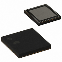
EM351-RTR Ember, EM351-RTR Datasheet - Page 159

EM351-RTR
Manufacturer Part Number
EM351-RTR
Description
IC RF TXRX ZIGBEE 128KB 48QFN
Manufacturer
Ember
Specifications of EM351-RTR
Frequency
2.4GHz
Data Rate - Maximum
250kbps
Modulation Or Protocol
802.15.4 Zigbee
Power - Output
3dBm
Sensitivity
-100dBm
Voltage - Supply
2.1 V ~ 3.6 V
Current - Receiving
26mA
Current - Transmitting
31mA
Data Interface
PCB, Surface Mount
Memory Size
128kB Flash, 12kB RAM
Antenna Connector
PCB, Surface Mount
Operating Temperature
-40°C ~ 85°C
Package / Case
48-QFN
Lead Free Status / RoHS Status
Lead free / RoHS Compliant
Applications
-
Other names
636-1010-2
Available stocks
Company
Part Number
Manufacturer
Quantity
Price
Company:
Part Number:
EM351-RTR
Manufacturer:
SILICONLABOR
Quantity:
4 550
- Current page: 159 of 245
- Download datasheet (12Mb)
Bitname
TIM_ETF
TIM_MSM
TIM_TS
TIM_SMS
Bitfield
[11:8]
[6:4]
[2:0]
[7]
Access
RW
RW
RW
RW
Description
External Trigger Filter.
This defines the frequency used to sample the ETRP signal, Fsampling, and the length of
the digital filter applied to ETRP. The digital filter is made of an event counter in which N
events are needed to validate a transition on the output:
0000: Fsampling=PCLK, no filtering.
0001: Fsampling=PCLK, N=2.
0010: Fsampling=PCLK, N=4.
0011: Fsampling=PCLK, N=8.
0100: Fsampling=PCLK/2, N=6.
0101: Fsampling=PCLK/2, N=8.
0110: Fsampling=PCLK/4, N=6.
0111: Fsampling=PCLK/4, N=8.
1000: Fsampling=PCLK/8, N=6.
1001: Fsampling=PCLK/8, N=8.
1010: Fsampling=PCLK/16, N=5.
1011: Fsampling=PCLK/16, N=6.
1100: Fsampling=PCLK/16, N=8.
1101: Fsampling=PCLK/32, N=5.
1110: Fsampling=PCLK/32, N=6.
1111: Fsampling=PCLK/32, N=8.
Note: PCLK is 12 MHz when the EM35x is using the 24 MHz crystal oscillator, and 6 MHz if
using the 12 MHz RC oscillator.
Master/Slave Mode.
0: No action.
1: The effect of an event on the trigger input (TRGI) is delayed to allow exact
synchronization between the current timer and the slave (through TRGO). It is useful for
synchronizing timers on a single external event.
Trigger Selection.
This bit field selects the trigger input used to synchronize the counter.
000 : Internal Trigger 0 (ITR0).
100 : TI1 Edge Detector (TI1F_ED).
101 : Filtered Timer Input 1 (TI1FP1).
110 : Filtered Timer Input 2 (TI2FP2).
111 : External Trigger input (ETRF).
Note: These bits must be changed only when they are not used (when TIM_SMS=000) to
avoid detecting spurious edges during the transition.
Slave Mode Selection.
When external signals are selected the active edge of the trigger signal (TRGI) is linked to
the polarity selected on the external input.
000: Slave mode disabled.
If TIM_CEN = 1 then the prescaler is clocked directly by the internal clock.
001: Encoder mode 1. Counter counts up/down on TI1FP1 edge depending on TI2FP2
level.
010: Encoder mode 2. Counter counts up/down on TI2FP2 edge depending on TI1FP1
level.
011: Encoder mode 3. Counter counts up/down on both TI1FP1 and TI2FP2 edges
depending on the level of the other input.
100: Reset Mode. Rising edge of the selected trigger signal (TRGI) >reinitializes the
counter and generates an update of the registers.
101: Gated Mode. The counter clock is enabled when the trigger signal (TRGI) is high. The
counter stops (but is not reset) as soon as the trigger becomes low. Both starting and
stopping the counter are controlled.
110: Trigger Mode. The counter starts at a rising edge of the trigger TRGI (but it is not
reset). Only starting the counter is controlled.
111: External Clock Mode 1. Rising edges of the selected trigger (TRGI) clock the counter.
Note: Gated mode must not be used if TI1F_ED is selected as the trigger input
(TIM_TS=100). TI1F_ED outputs 1 pulse for each transition on TI1F, whereas gated mode
checks the level of the trigger signal.
Final
9-35
120-035X-000G
Related parts for EM351-RTR
Image
Part Number
Description
Manufacturer
Datasheet
Request
R

Part Number:
Description:
MODULE EM351 NO PA/LNA W/ANT TG
Manufacturer:
Ember
Datasheet:

Part Number:
Description:
MODULE EM351 NO PA/LNA W/RF CONN
Manufacturer:
Ember
Datasheet:

Part Number:
Description:
MODULE EM351 PA/LNA W/ANT TG
Manufacturer:
Ember
Datasheet:

Part Number:
Description:
MODULE EM351 PA/LNA W/RF CONN
Manufacturer:
Ember
Datasheet:

Part Number:
Description:
KIT DEV EMBER ZIGBEE W/PCWH
Manufacturer:
Custom Computer Services Inc (CCS)

Part Number:
Description:
PROGRAMMER USB FLASH EM250/260
Manufacturer:
Ember
Datasheet:

Part Number:
Description:
IC ZIGBEE SYSTEM-ON-CHIP 40-QFN
Manufacturer:
Ember
Datasheet:

Part Number:
Description:
IC ZIGBEE SYSTEM-ON-CHIP 48-QFN
Manufacturer:
Ember
Datasheet:

Part Number:
Description:
IC RF TXRX ZIGBEE 192KB 48QFN
Manufacturer:
Ember
Datasheet:

Part Number:
Description:
INSIGHT ADAPTER FOR EM2XX
Manufacturer:
Ember
Datasheet:

Part Number:
Description:
IAR EWARM LICENCE FOR EM35X
Manufacturer:
Ember
Datasheet:

Part Number:
Description:
PROGRAMMER USB FLASH EM250/260
Manufacturer:
Ember
Datasheet:

Part Number:
Description:
IC ZIGBEE SYSTEM-ON-CHIP 40-QFN
Manufacturer:
Ember
Datasheet:

Part Number:
Description:
IC ZIGBEE SYSTEM-ON-CHIP 48-QFN
Manufacturer:
Ember
Datasheet:

Part Number:
Description:
IC RF TXRX ZIGBEE 192KB 48QFN
Manufacturer:
Ember
Datasheet:


