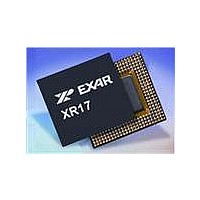
XR17V354IB176-F Exar Corporation, XR17V354IB176-F Datasheet - Page 45

XR17V354IB176-F
Manufacturer Part Number
XR17V354IB176-F
Description
IC UART PCIE 256B DUAL 176FPBGA
Manufacturer
Exar Corporation
Datasheet
1.XR17V354IB176-F.pdf
(66 pages)
Specifications of XR17V354IB176-F
Number Of Channels
4, QUART
Package / Case
176-LFBGA
Features
*
Fifo's
256 Byte
Protocol
RS485
Voltage - Supply
3.3V
With Auto Flow Control
Yes
With Irda Encoder/decoder
Yes
With False Start Bit Detection
Yes
With Modem Control
Yes
Mounting Type
Surface Mount
Data Rate
25 Mbps
Supply Current
120 mA
Maximum Operating Temperature
+ 85 C
Minimum Operating Temperature
- 40 C
Mounting Style
SMD/SMT
Operating Supply Voltage
3.3 V
No. Of Channels
4
Uart Features
Tx/Rx FIFO Counters
Supply Voltage Range
3V To 3.6V
Operating Temperature Range
-40°C To +85°C
Digital Ic Case Style
BGA
No. Of Pins
176
Rohs Compliant
Yes
Lead Free Status / RoHS Status
Lead free / RoHS Compliant
Lead Free Status / RoHS Status
Lead free / RoHS Compliant, Lead free / RoHS Compliant
Available stocks
Company
Part Number
Manufacturer
Quantity
Price
Company:
Part Number:
XR17V354IB176-F
Manufacturer:
EXAR
Quantity:
500
Company:
Part Number:
XR17V354IB176-F
Manufacturer:
Exar Corporation
Quantity:
10 000
Part Number:
XR17V354IB176-F
Manufacturer:
EXAR/艾科嘉
Quantity:
20 000
REV. 1.0.1
Normal multidrop mode is enabled when DLD[6] = 1 and EFR[5] = 0 (Special Character Detect disabled). The
receiver is set to Force Parity 0 (LCR[5:3] = ’111’) in order to detect address bytes.
With the receiver initially disabled (MSR[2] = 1), it ignores all the data bytes (parity bit = 0) until an address byte
is received (parity bit = 1). This address byte will cause the UART to set the parity error. The UART will
generate an LSR interrupt and place the address byte in the RX FIFO. The software then examines the byte
and enables the receiver if the address matches its slave address, otherwise, it does not enable the receiver.
If the receiver has been enabled, the receiver will receive the subsequent data. If an address byte is received,
it will generate an LSR interrupt. The software again examines the byte and if the address matches its slave
address, it does not have to do anything. If the address does not match its slave address, then the receiver
should be disabled.
Auto address detection mode is enabled when DLD[6] = 1 and EFR bit-5 = 1 (Special Character Detect
enabled). The receiver is set to Force Parity 0 (LCR[5:3] = ’111’) in order to detect address bytes. The desired
slave address will need to be written into the XOFF2 register. The receiver will monitor all incoming address
bytes and compare with the programmed character in the XOFF2 register. If the received byte is a data byte or
an address byte that does not match the programmed character in the XOFF2 register, the receiver will discard
the data. Upon receiving an address byte that matches the XOFF2 character, the receiver will be automatically
enabled if not already enabled, and the address character is pushed into the RX FIFO along with the parity bit
(in place of the parity error bit). The receiver also generates an LSR interrupt. The receiver will then receive
the subsequent data. If another address byte is received and this address does not match the programmed
XOFF2 character, then the receiver will automatically be disabled and all subsequent data is ignored until there
is another address byte match with XOFF2.
F
3.7.2
3.7.3
3.7.4
IGURE
Receive Data
Byte and Errors
16X or 8X or 4X
16. R
11-bits wide FIFO
Receiver Operation with FIFO
Normal Multidrop (9-bit) Mode
Auto Address Detection Mode
256 bytes by
Clock
ECEIVER
O
PERATION IN
Receive Data Shift
Register (RSR)
Receive Data
(256-byte)
Receive
FIFO
FIFO
Data
AND
F
Data fills to 160
FIFO Trigger=128
Data falls to 96
LOW
Validation
Data Bit
Example:
- FIFO trigger level set at 128 bytes
- RTS/DTR hyasteresis set at +/-32 chars.
C
45
ONTROL
HIGH PERFORMANCE QUAD PCI-EXPRESS UART
Enable by EFR bit-6=1, MCR bit-2.
Enable by EFR bit-6=1, MCR bit-2.
M
RTS#/DTR# re-asserts when data falls below
the trigger level to restart remote transmitter.
RTS#/DTR# de-asserts when data fills above
the trigger level to suspend remote transmitter.
at FIFO trigger level (RXTRG).
FIFO is Enable by FCR bit-0=1
RHR Interrupt (ISR bit-2) is programmed
ODE
Receive Data Characters
XR17V354


