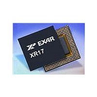
XR17V354IB176-F Exar Corporation, XR17V354IB176-F Datasheet - Page 56

XR17V354IB176-F
Manufacturer Part Number
XR17V354IB176-F
Description
IC UART PCIE 256B DUAL 176FPBGA
Manufacturer
Exar Corporation
Datasheet
1.XR17V354IB176-F.pdf
(66 pages)
Specifications of XR17V354IB176-F
Number Of Channels
4, QUART
Package / Case
176-LFBGA
Features
*
Fifo's
256 Byte
Protocol
RS485
Voltage - Supply
3.3V
With Auto Flow Control
Yes
With Irda Encoder/decoder
Yes
With False Start Bit Detection
Yes
With Modem Control
Yes
Mounting Type
Surface Mount
Data Rate
25 Mbps
Supply Current
120 mA
Maximum Operating Temperature
+ 85 C
Minimum Operating Temperature
- 40 C
Mounting Style
SMD/SMT
Operating Supply Voltage
3.3 V
No. Of Channels
4
Uart Features
Tx/Rx FIFO Counters
Supply Voltage Range
3V To 3.6V
Operating Temperature Range
-40°C To +85°C
Digital Ic Case Style
BGA
No. Of Pins
176
Rohs Compliant
Yes
Lead Free Status / RoHS Status
Lead free / RoHS Compliant
Lead Free Status / RoHS Status
Lead free / RoHS Compliant, Lead free / RoHS Compliant
Available stocks
Company
Part Number
Manufacturer
Quantity
Price
Company:
Part Number:
XR17V354IB176-F
Manufacturer:
EXAR
Quantity:
500
Company:
Part Number:
XR17V354IB176-F
Manufacturer:
Exar Corporation
Quantity:
10 000
Part Number:
XR17V354IB176-F
Manufacturer:
EXAR/艾科嘉
Quantity:
20 000
XR17V354
HIGH PERFORMANCE QUAD PCI-EXPRESS UART
MSR[3]: Delta CD# Input Flag
•
•
MSR[2]: Delta RI# Input Flag
•
•
MSR[1]: Delta DSR# Input Flag
•
•
MSR[0]: Delta CTS# Input Flag
•
•
The upper four bits [7:4] of this register set the delay in number of bits time for the auto RS-485 turn around
from transmit to receive.
MSR [7:4]: Auto RS485 Turn-Around Delay (requires EFR bit [4]=1)
When Auto RS485 feature is enabled (FCTR bit [5]=1) and RTS#/DTR# output is connected to the enable input
of a RS-485 transceiver. These 4 bits select from 0 to 15 bit-time delay after the end of the last stop-bit of the
last transmitted character. This delay controls when to change the state of RTS#/DTR# output. This delay is
very useful in long-cable networks.
4.11
Logic 0 = No change on CD# input (default).
Logic 1 = Indicates that the CD# input has changed state since the last time it was monitored. A modem
status interrupt will be generated if MSR interrupt is enabled (IER bit [3]).
Logic 0 = No change on RI# input (default).
Logic 1 = The RI# input has changed from a LOW to a HIGH, ending of the ringing signal. A modem status
interrupt will be generated if MSR interrupt is enabled (IER bit [3]).
Logic 0 = No change on DSR# input (default).
Logic 1 = The DSR# input has changed state since the last time it was monitored. A modem status interrupt
will be generated if MSR interrupt is enabled (IER bit [3]).
Logic 0 = No change on CTS# input (default).
Logic 1 = The CTS# input has changed state since the last time it was monitored. A modem status interrupt
will be generated if MSR interrupt is enabled (IER bit [3]).
Modem Status Register (MSR) - Write Only
Table 18
shows the selection. The bits are enabled by EFR bit-4.
56
REV. 1.0.1


