OM13012,598 NXP Semiconductors, OM13012,598 Datasheet - Page 26
OM13012,598
Manufacturer Part Number
OM13012,598
Description
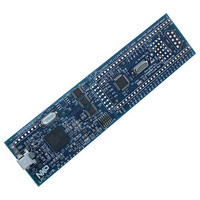
BOARD EVAL LPC11C2X
Manufacturer
NXP Semiconductors
Datasheet
1.LPC11C14FBD48301.pdf
(61 pages)
Specifications of OM13012,598
Featured Product
32-bit ARM Cortex-M0 Microcontrollers
Processor To Be Evaluated
LPC11C2x
Data Bus Width
32 bit
Core
ARM Cortex-M0
Maximum Operating Temperature
+ 85 C
Minimum Operating Temperature
- 40 C
Operating Supply Voltage
3.3 V
Lead Free Status / RoHS Status
Lead free / RoHS Compliant
Lead Free Status / RoHS Status
Lead free / RoHS Compliant, Lead free / RoHS Compliant
Other names
568-6645
OM13012
OM13012


NXP Semiconductors
LPC11CX2_CX4
Product data sheet
CAUTION
7.17.4 Code security (Code Read Protection - CRP)
7.17.5 Bootloader
NVIC in order to cause a CPU interrupt; if not, software can monitor the signal by reading
a dedicated status register. Four additional threshold levels can be selected to cause a
forced reset of the chip.
This feature of the LPC11Cx2/Cx4 allows user to enable different levels of security in the
system so that access to the on-chip flash and use of the Serial Wire Debugger (SWD)
and In-System Programming (ISP) can be restricted. When needed, CRP is invoked by
programming a specific pattern into a dedicated flash location. IAP commands are not
affected by the CRP.
In addition, ISP entry via the PIO0_1 pin can be disabled without enabling CRP. For
details see the LPC11Cx user manual.
There are three levels of Code Read Protection:
In addition to the three CRP levels, sampling of pin PIO0_1 for valid user code can be
disabled. For details see the LPC11Cx user manual.
The bootloader controls initial operation after reset and also provides the means to
program the flash memory. This could be initial programming of a blank device, erasure
and re-programming of a previously programmed device, or programming of the flash
memory by the application program in a running system.
The bootloader code is executed every time the part is reset or powered up. The loader
can either execute the user application code or the ISP command handler via UART or
C_CAN. A LOW level during reset applied to the PIO0_1 pin is considered as an external
hardware request to start the ISP command handler. The state of PIO0_3 at reset
determines whether the UART (PIO0_3 HIGH) or the C_CAN (PIO0_3 LOW) interface will
be used.
1. CRP1 disables access to the chip via the SWD and allows partial flash update
2. CRP2 disables access to the chip via the SWD and only allows full flash erase and
3. Running an application with level CRP3 selected fully disables any access to the chip
(excluding flash sector 0) using a limited set of the ISP commands. This mode is
useful when CRP is required and flash field updates are needed but all sectors can
not be erased.
update using a reduced set of the ISP commands.
via the SWD pins and the ISP. This mode effectively disables ISP override using
PIO0_1 pin, too. It is up to the user’s application to provide (if needed) flash update
mechanism using IAP calls or call reinvoke ISP command to enable flash update via
the UART.
If level three Code Read Protection (CRP3) is selected, no future factory testing can be
performed on the device.
All information provided in this document is subject to legal disclaimers.
Rev. 2 — 3 December 2010
32-bit ARM Cortex-M0 microcontroller
LPC11Cx2/Cx4
© NXP B.V. 2010. All rights reserved.
26 of 61
Related parts for OM13012,598
Image
Part Number
Description
Manufacturer
Datasheet
Request
R

Part Number:
Description:
NXP Semiconductors designed the LPC2420/2460 microcontroller around a 16-bit/32-bitARM7TDMI-S CPU core with real-time debug interfaces that include both JTAG andembedded trace
Manufacturer:
NXP Semiconductors
Datasheet:

Part Number:
Description:
NXP Semiconductors designed the LPC2458 microcontroller around a 16-bit/32-bitARM7TDMI-S CPU core with real-time debug interfaces that include both JTAG andembedded trace
Manufacturer:
NXP Semiconductors
Datasheet:
Part Number:
Description:
NXP Semiconductors designed the LPC2468 microcontroller around a 16-bit/32-bitARM7TDMI-S CPU core with real-time debug interfaces that include both JTAG andembedded trace
Manufacturer:
NXP Semiconductors
Datasheet:
Part Number:
Description:
NXP Semiconductors designed the LPC2470 microcontroller, powered by theARM7TDMI-S core, to be a highly integrated microcontroller for a wide range ofapplications that require advanced communications and high quality graphic displays
Manufacturer:
NXP Semiconductors
Datasheet:
Part Number:
Description:
NXP Semiconductors designed the LPC2478 microcontroller, powered by theARM7TDMI-S core, to be a highly integrated microcontroller for a wide range ofapplications that require advanced communications and high quality graphic displays
Manufacturer:
NXP Semiconductors
Datasheet:
Part Number:
Description:
The Philips Semiconductors XA (eXtended Architecture) family of 16-bit single-chip microcontrollers is powerful enough to easily handle the requirements of high performance embedded applications, yet inexpensive enough to compete in the market for hi
Manufacturer:
NXP Semiconductors
Datasheet:
Part Number:
Description:
The XA-S3 device is a member of Philips Semiconductors? XA(eXtended Architecture) family of high performance 16-bitsingle-chip microcontrollers
Manufacturer:
NXP Semiconductors
Datasheet:

Part Number:
Description:
The NXP BlueStreak LH75401/LH75411 family consists of two low-cost 16/32-bit System-on-Chip (SoC) devices
Manufacturer:
NXP Semiconductors
Datasheet:
Part Number:
Description:
The NXP LPC3130/3131 combine an 180 MHz ARM926EJ-S CPU core, high-speed USB2
Manufacturer:
NXP Semiconductors
Datasheet:
Part Number:
Description:
The NXP LPC3141 combine a 270 MHz ARM926EJ-S CPU core, High-speed USB 2
Manufacturer:
NXP Semiconductors
Part Number:
Description:
The NXP LPC3143 combine a 270 MHz ARM926EJ-S CPU core, High-speed USB 2
Manufacturer:
NXP Semiconductors

Part Number:
Description:
The NXP LPC3152 combines an 180 MHz ARM926EJ-S CPU core, High-speed USB 2
Manufacturer:
NXP Semiconductors
Part Number:
Description:
The NXP LPC3154 combines an 180 MHz ARM926EJ-S CPU core, High-speed USB 2
Manufacturer:
NXP Semiconductors

Part Number:
Description:
Standard level N-channel enhancement mode Field-Effect Transistor (FET) in a plastic package using NXP High-Performance Automotive (HPA) TrenchMOS technology
Manufacturer:
NXP Semiconductors
Datasheet: