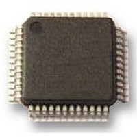
DP83848VYB National Semiconductor, DP83848VYB Datasheet - Page 30

DP83848VYB
Manufacturer Part Number
DP83848VYB
Description
TRANSCEIVER, ENET PHY, 10/100, 48LQFP
Manufacturer
National Semiconductor
Datasheet
1.DP83848VYB.pdf
(76 pages)
Specifications of DP83848VYB
Data Rate
100Mbps
No. Of Ports
1
Ethernet Type
IEEE 802.3u
Supply Current
92mA
Supply Voltage Range
3V To 3.6V
Operating Temperature Range
-40°C To +105°C
Digital Ic Case Style
LQFP
No.
RoHS Compliant
Interface Type
MII Serial, RMII
Rohs Compliant
Yes
Lead Free Status / Rohs Status
Not Compliant
Available stocks
Company
Part Number
Manufacturer
Quantity
Price
Company:
Part Number:
DP83848VYB/NOPB
Manufacturer:
NS
Quantity:
570
Company:
Part Number:
DP83848VYB/NOPB
Manufacturer:
Texas Instruments
Quantity:
10 000
www.national.com
5.5 POWER DOWN/INTERRUPT
The Power Down and Interrupt functions are multiplexed on
pin 7 of the device. By default, this pin functions as a power
down input and the interrupt function is disabled. Setting bit 0
(INT_OE) of MICR (0x11h) will configure the pin as an active
low interrupt output.
5.5.1 Power Down Control Mode
The PWRDOWN_INT pins can be asserted low to put the de-
vice in a Power Down mode. This is equivalent to setting bit
11 (Power Down) in the Basic Mode Control Register, BMCR
(0x00h). An external control signal can be used to drive the
pin low, overcoming the weak internal pull-up resistor. Alter-
natively, the device can be configured to initialize into a Power
Down state by use of an external pull-down resistor on the
PWRDOWN_INT pin. Since the device will still respond to
management register accesses, setting the INT_OE bit in the
MICR register will disable the PWRDOWN_INT input, allow-
ing the device to exit the Power Down state.
5.5.2 Interrupt Mechanisms
The interrupt function is controlled via register access. All in-
terrupt sources are disabled by default. Setting bit 1 (INTEN)
of MICR (0x11h) will enable interrupts to be output, depen-
FIGURE 12. Power Feedback Connection
30011713
30
dent on the interrupt mask set in the lower byte of the MISR
(0x12h). The PWRDOWN_INT pin is asynchronously assert-
ed low when an interrupt condition occurs. The source of the
interrupt can be determined by reading the upper byte of the
MISR. One or more bits in the MISR will be set, denoting all
currently pending interrupts. Reading of the MISR clears ALL
pending interrupts.
Example: To generate an interrupt on a change of link status
or on a change of energy detect power state, the steps would
be:
•
•
•
When PWRDOWN_INT pin asserts low, the user would read
the MISR register to see if the ED_INT or LINK_INT bits are
set, i.e. which source caused the interrupt. After reading the
MISR,
PWRDOWN_INT pin will deassert.
5.6 ENERGY DETECT MODE
When Energy Detect is enabled and there is no activity on the
cable, the DP83848VYB will remain in a low power mode
while monitoring the transmission line. Activity on the line will
cause the DP83848VYB to go through a normal power up
sequence. Regardless of cable activity, the DP83848VYB will
occasionally wake up the transmitter to put ED pulses on the
line, but will otherwise draw as little power as possible. Energy
detect functionality is controlled via register Energy Detect
Control (EDCR), address 0x1Dh.
5.7 THERMAL Vias RECOMMENDATION
The following thermal via guidelines apply to GNDPAD, pin
49:
1.
2.
3.
Adherence to this guideline is required to achieve the intend-
ed operating temperature range of the device.
Figure 13 illustrates an example layout.
Write 0003h to MICR to set INTEN and INT_OE
Write 0060h to MISR to set ED_INT_EN and
LINK_INT_EN
Monitor PWRDOWN_INT pin
Thermal via size = 0.2 mm
Recommend 4 vias
Vias have a center to center separation of 2 mm.
the
interrupt
bits
should
clear
and
the


