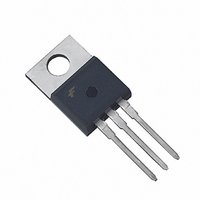
HGTP5N120BND Fairchild Semiconductor, HGTP5N120BND Datasheet - Page 6

HGTP5N120BND
Manufacturer Part Number
HGTP5N120BND
Description
IGBT NPT N-CH 1200V 21A TO-220AB
Manufacturer
Fairchild Semiconductor
Datasheet
1.HGTP5N120BND.pdf
(8 pages)
Specifications of HGTP5N120BND
Igbt Type
NPT
Voltage - Collector Emitter Breakdown (max)
1200V
Vce(on) (max) @ Vge, Ic
2.7V @ 15V, 5A
Current - Collector (ic) (max)
21A
Power - Max
167W
Input Type
Standard
Mounting Type
Through Hole
Package / Case
TO-220-3 (Straight Leads)
Channel Type
N
Configuration
Single
Collector-emitter Voltage
1.2kV
Gate To Emitter Voltage (max)
±20V
Package Type
TO-220AB
Pin Count
3 +Tab
Mounting
Through Hole
Operating Temperature (min)
-55
Operating Temperature (max)
150C
Operating Temperature Classification
Military
Collector- Emitter Voltage Vceo Max
1200 V
Collector-emitter Saturation Voltage
2.45 V
Maximum Gate Emitter Voltage
+/- 20 V
Continuous Collector Current At 25 C
21 A
Gate-emitter Leakage Current
+/- 250 nA
Power Dissipation
167 W
Maximum Operating Temperature
+ 150 C
Continuous Collector Current Ic Max
21 A
Minimum Operating Temperature
- 55 C
Mounting Style
Through Hole
Lead Free Status / RoHS Status
Lead free / RoHS Compliant
Available stocks
Company
Part Number
Manufacturer
Quantity
Price
Company:
Part Number:
HGTP5N120BND
Manufacturer:
FSC
Quantity:
10 000
Part Number:
HGTP5N120BND
Manufacturer:
FAIRCHILD/仙童
Quantity:
20 000
Typical Performance Curves
©2003 Fairchild Semiconductor Corporation
FIGURE 15. CAPACITANCE vs COLLECTOR TO EMITTER
FIGURE 18. DIODE FORWARD CURRENT vs FORWARD
100
10
2.0
1.5
1.0
0.5
1
0
0
0
10
10
10
FREQUENCY = 1MHz
C
25
-1
-2
0
RES
10
o
C
C
C
-5
OES
0.02
0.01
IES
0.05
V
VOLTAGE
0.5
0.1
1
VOLTAGE DROP
0.2
CE
150
5
, COLLECTOR TO EMITTER VOLTAGE (V)
o
C
2
V
F
-55
SINGLE PULSE
, FORWARD VOLTAGE (V)
FIGURE 17. NORMALIZED TRANSIENT THERMAL RESPONSE, JUNCTION TO CASE
o
C
10
3
10
4
-4
15
5
Unless Otherwise Specified (Continued)
6
20
t
1
, RECTANGULAR PULSE DURATION (s)
7
10
25
-3
8
FIGURE 16. COLLECTOR TO EMITTER ON-STATE VOLTAGE
DUTY FACTOR, D = t
PEAK T
FIGURE 19. RECOVERY TIMES vs FORWARD CURRENT
60
50
40
30
20
10
10
0
8
6
4
2
0
10
1
0
J
-2
DUTY CYCLE < 0.5%, T
PULSE DURATION = 250 s
= (P
T
C
0.5
V
D
= 25
CE
x Z
2
, COLLECTOR TO EMITTER VOLTAGE (V)
o
1.0
C, dl
JC
1
/ t
x R
I
EC
F
2
1.5
, FORWARD CURRENT (A)
/ dt = 200A/ s
3
JC
t rr
) + T
t a
t b
2.0
C
HGTG5N120BND, HGTP5N120BND, Rev. B1
10
= 110
V
C
GE
-1
4
2.5
= 15V
P
o
D
C
3.0
5
t
1
t
3.5
2
V
GE
4.0
6
= 10V
10
4.5
0
7


