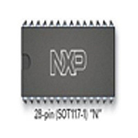
SJA1000 NXP Semiconductors, SJA1000 Datasheet - Page 16

SJA1000
Manufacturer Part Number
SJA1000
Description
Manufacturer
NXP Semiconductors
Datasheet
1.SJA1000.pdf
(68 pages)
Specifications of SJA1000
Data Rate
1000Kbps
Number Of Transceivers
1
Power Down Mode
Sleep
Standard Supported
CAN 2.0B
Operating Supply Voltage (max)
5.5V
Operating Supply Voltage (typ)
5V
Operating Supply Voltage (min)
4.5V
Package Type
PDIP
Supply Current
15mA
Operating Temperature (max)
125C
Operating Temperature (min)
-40C
Operating Temperature Classification
Automotive
Mounting
Through Hole
Pin Count
28
Lead Free Status / RoHS Status
Compliant
Available stocks
Company
Part Number
Manufacturer
Quantity
Price
Part Number:
SJA1000
Manufacturer:
PHILIPS/飞利浦
Quantity:
20 000
Company:
Part Number:
SJA1000N
Manufacturer:
NXP
Quantity:
5 510
Part Number:
SJA1000N
Manufacturer:
PHILIPS/飞利浦
Quantity:
20 000
Part Number:
SJA1000T
Manufacturer:
NXP
Quantity:
20 000
Part Number:
SJA1000T SJ
Manufacturer:
NXP/恩智浦
Quantity:
20 000
Part Number:
SJA1000T/N1
Manufacturer:
NXP/恩智浦
Quantity:
20 000
Company:
Part Number:
SJA1000T/N1,118
Manufacturer:
XILINX
Quantity:
125
Philips Semiconductors
Notes
1. When the transmit error counter exceeds the limit of 255 [the bus status bit is set to logic 1 (bus-off)] the
2. Errors detected during reception or transmission will affect the error counters according to the CAN 2.0B protocol
3. If both the receive status and the transmit status bits are logic 0 (idle) the CAN-bus is idle.
4. The transmission complete status bit is set to logic 0 (incomplete) whenever the transmission request bit is set to
5. If the CPU tries to write to the transmit buffer when the transmit buffer status bit is at logic 0 (locked), the written byte
6. When a message that shall be received has passed the acceptance filter successfully (i.e. earliest after arbitration
7. After reading a message stored in the RXFIFO and releasing this memory space with the command release receive
2000 Jan 04
Stand-alone CAN controller
CAN controller will set the reset request bit to logic 1 (present) and an error interrupt is generated, if enabled. It will
stay in this mode until the CPU clears the reset request bit. Once this is completed the CAN controller will wait the
minimum protocol-defined time (128 occurrences of the bus-free signal). After that the bus status bit is cleared
(bus-on), the error status bit is set to logic 0 (ok), the error counters are reset and an error interrupt is generated, if
enabled.
specification. The error status bit is set when at least one of the error counters has reached or exceeded the CPU
warning limit of 96. An error interrupt is generated, if enabled.
logic 1. The transmission complete status bit will remain at logic 0 (incomplete) until a message is transmitted
successfully.
will not be accepted and will be lost without being indicated.
field), the CAN controller needs space in the RXFIFO to store the message descriptor. Accordingly there must be
enough space for each data byte which has been received. If there is not enough space to store the message, that
message will be dropped and the data overrun condition will be indicated to the CPU only, if this received message
has no errors until the last but one bit of end of frame (message becomes valid).
buffer, this bit is cleared. If there is another message available within the FIFO this bit is set again with the next bit
quantum (t
scl
).
16
Product specification
SJA1000


