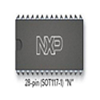
SJA1000 NXP Semiconductors, SJA1000 Datasheet - Page 8

SJA1000
Manufacturer Part Number
SJA1000
Description
Manufacturer
NXP Semiconductors
Datasheet
1.SJA1000.pdf
(68 pages)
Specifications of SJA1000
Data Rate
1000Kbps
Number Of Transceivers
1
Power Down Mode
Sleep
Standard Supported
CAN 2.0B
Operating Supply Voltage (max)
5.5V
Operating Supply Voltage (typ)
5V
Operating Supply Voltage (min)
4.5V
Package Type
PDIP
Supply Current
15mA
Operating Temperature (max)
125C
Operating Temperature (min)
-40C
Operating Temperature Classification
Automotive
Mounting
Through Hole
Pin Count
28
Lead Free Status / RoHS Status
Compliant
Available stocks
Company
Part Number
Manufacturer
Quantity
Price
Part Number:
SJA1000
Manufacturer:
PHILIPS/飞利浦
Quantity:
20 000
Company:
Part Number:
SJA1000N
Manufacturer:
NXP
Quantity:
5 510
Part Number:
SJA1000N
Manufacturer:
PHILIPS/飞利浦
Quantity:
20 000
Part Number:
SJA1000T
Manufacturer:
NXP
Quantity:
20 000
Part Number:
SJA1000T SJ
Manufacturer:
NXP/恩智浦
Quantity:
20 000
Part Number:
SJA1000T/N1
Manufacturer:
NXP/恩智浦
Quantity:
20 000
Company:
Part Number:
SJA1000T/N1,118
Manufacturer:
XILINX
Quantity:
125
Philips Semiconductors
6.2.1.3
The dual receive buffer concept of the PCA82C200 is
replaced by the receive FIFO from the PeliCAN controller.
This has no effect to the application software except for the
data overrun probability. Now more than two messages
may be received (up to 64 bytes) until a data overrun
occurs.
6.2.1.4
The SJA1000 is designed to support the full CAN 2.0B
protocol specification, which means that the extended
oscillator tolerance is implemented as well as the
processing of extended frame messages. In BasicCAN
mode it is possible to transmit and receive standard frame
messages only (11-bit identifier). If extended frame
messages (29-bit identifier) are detected on the CAN-bus,
they are tolerated and an acknowledge is given if the
message was correct, but there is no receive interrupt
generated.
6.2.2
In the PeliCAN mode the SJA1000 appears with a
re-organized register mapping with a lot of new features.
All known bits from the PCA82C200 design are available
as well as several new ones. In the PeliCAN mode the
complete CAN 2.0B functionality is supported (29-bit
identifier).
Main new features of the SJA1000 are:
2000 Jan 04
Reception and transmission of standard and extended
frame format messages
Receive FIFO (64-byte)
Single/dual acceptance filter with mask and code
register for standard and extended frame
Error counters with read/write access
Programmable error warning limit
Last error code register
Error interrupt for each CAN-bus error
Arbitration lost interrupt with detailed bit position
Single-shot transmission (no re-transmission on error or
arbitration lost)
Listen only mode (monitoring of the CAN-bus, no
acknowledge, no error flags)
Hot plugging supported (disturbance-free software
driven bit rate detection)
Disable CLKOUT by hardware.
Stand-alone CAN controller
D
MODE
IFFERENCES BETWEEN
Receive buffer
CAN 2.0B
B
ASIC
CAN
AND
P
ELI
CAN
8
6.3
6.3.1
The SJA1000 appears to a microcontroller as a
memory-mapped I/O device. An independent operation of
both devices is guaranteed by a RAM-like implementation
of the on-chip registers.
The address area of the SJA1000 consists of the control
segment and the message buffers. The control segment is
programmed during an initialization download in order to
configure communication parameters (e.g. bit timing).
Communication over the CAN-bus is also controlled via
this segment by the microcontroller. During initialization
the CLKOUT signal may be programmed to a value
determined by the microcontroller.
A message, which should be transmitted, has to be written
to the transmit buffer. After a successful reception the
microcontroller may read the received message from the
receive buffer and then release it for further use.
The exchange of status, control and command signals
between the microcontroller and the SJA1000 is
performed in the control segment. The layout of this
segment is shown in Table 3. After an initial download, the
contents of the registers acceptance code, acceptance
mask, bus timing registers 0 and 1 and output control
should not be changed. Therefore these registers may
only be accessed when the reset request bit in the control
register is set HIGH.
For register access, two different modes have to be
distinguished:
The reset mode (see Table 3, control register, bit Reset
Request) is entered automatically after a hardware reset
or when the controller enters the bus-off state (see
Table 5, status register, bit Bus Status). The operating
mode is activated by resetting of the reset request bit in the
control register.
Reset mode
Operating mode.
BasicCAN mode
B
ASIC
CAN
ADDRESS LAYOUT
Product specification
SJA1000


