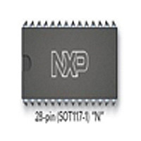
SJA1000 NXP Semiconductors, SJA1000 Datasheet - Page 38

SJA1000
Manufacturer Part Number
SJA1000
Description
Manufacturer
NXP Semiconductors
Datasheet
1.SJA1000.pdf
(68 pages)
Specifications of SJA1000
Data Rate
1000Kbps
Number Of Transceivers
1
Power Down Mode
Sleep
Standard Supported
CAN 2.0B
Operating Supply Voltage (max)
5.5V
Operating Supply Voltage (typ)
5V
Operating Supply Voltage (min)
4.5V
Package Type
PDIP
Supply Current
15mA
Operating Temperature (max)
125C
Operating Temperature (min)
-40C
Operating Temperature Classification
Automotive
Mounting
Through Hole
Pin Count
28
Lead Free Status / RoHS Status
Compliant
Available stocks
Company
Part Number
Manufacturer
Quantity
Price
Part Number:
SJA1000
Manufacturer:
PHILIPS/飞利浦
Quantity:
20 000
Company:
Part Number:
SJA1000N
Manufacturer:
NXP
Quantity:
5 510
Part Number:
SJA1000N
Manufacturer:
PHILIPS/飞利浦
Quantity:
20 000
Part Number:
SJA1000T
Manufacturer:
NXP
Quantity:
20 000
Part Number:
SJA1000T SJ
Manufacturer:
NXP/恩智浦
Quantity:
20 000
Part Number:
SJA1000T/N1
Manufacturer:
NXP/恩智浦
Quantity:
20 000
Company:
Part Number:
SJA1000T/N1,118
Manufacturer:
XILINX
Quantity:
125
Philips Semiconductors
Table 22 Bit interpretation of the error warning limit register (EWLR); CAN address 13
6.4.11
The RX error counter register reflects the current value of the receive error counter. After a hardware reset this register
is initialized to logic 0. In operating mode this register appears to the CPU as a read only memory. A write access to this
register is possible only in reset mode.
If a bus-off event occurs, the RX error counter is initialized to logic 0. The time bus-off is valid, writing to this register has
no effect.
Note, that a CPU-forced content change of the RX error counter is only possible, if the reset mode was entered
previously. An error status change (see status register; Table 14), an error warning or an error passive interrupt forced
by the new register content will not occur, until the reset mode is cancelled again.
Table 23 Bit interpretation of the RX error counter register (RXERR); CAN address 14
6.4.12
The TX error counter register reflects the current value of the transmit error counter.
In operating mode this register appears to the CPU as a read only memory. A write access to this register is possible
only in reset mode. After a hardware reset this register is initialized to logic 0. If a bus-off event occurs, the TX error
counter is initialized to 127 to count the minimum protocol-defined time (128 occurrences of the bus-free signal). Reading
the TX error counter during this time gives information about the status of the bus-off recovery.
If bus-off is active, a write access to TXERR in the range from 0 to 254 clears the bus-off flag and the controller will wait
for one occurrence of 11 consecutive recessive bits (bus-free) after the reset mode has been cleared.
Table 24 Bit interpretation of the TX error counter register (TXERR); CAN address 15
Writing 255 to TXERR allows to initiate a CPU-driven bus-off event. It should be noted that a CPU-forced content change
of the TX error counter is only possible, if the reset mode was entered previously. An error or bus status change (see
status register; Table 14), an error warning or an error passive interrupt forced by the new register content will not occur
until the reset mode is cancelled again. After leaving the reset mode, the new TX counter content is interpreted and the
bus-off event is performed in the same way, as if it was forced by a bus error event. That means, that the reset mode is
entered again, the TX error counter is initialized to 127, the RX counter is cleared and all concerned status and interrupt
register bits are set.
Clearing of reset mode now will perform the protocol-defined bus-off recovery sequence (waiting for 128 occurrences of
the bus-free signal).
If the reset mode is entered again before the end of bus-off recovery (TXERR > 0), bus-off keeps active and TXERR is
frozen.
2000 Jan 04
Stand-alone CAN controller
RXERR.7
TXERR.7
EWL.7
BIT 7
BIT 7
BIT 7
RX E
TX E
RROR
RROR
RXERR.6
TXERR.6
EWL.6
BIT 6
BIT 6
BIT 6
C
C
OUNTER
OUNTER
R
R
EGISTER
EGISTER
RXERR.5
TXERR.5
EWL.5
BIT 5
BIT 5
BIT 5
(TXERR)
(RXERR)
RXERR.4
TXERR.4
EWL.4
BIT 4
BIT 4
BIT 4
38
RXERR.3
TXERR.3
EWL.3
BIT 3
BIT 3
BIT 3
RXERR.2
TXERR.2
EWL.2
BIT 2
BIT 2
BIT 2
RXERR.1
TXERR.1
EWL.1
BIT 1
BIT 1
BIT 1
Product specification
SJA1000
RXERR.0
TXERR.0
EWL.0
BIT 0
BIT 0
BIT 0


