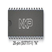
SJA1000 NXP Semiconductors, SJA1000 Datasheet - Page 37

SJA1000
Manufacturer Part Number
SJA1000
Description
Manufacturer
NXP Semiconductors
Datasheet
1.SJA1000.pdf
(68 pages)
Specifications of SJA1000
Data Rate
1000Kbps
Number Of Transceivers
1
Power Down Mode
Sleep
Standard Supported
CAN 2.0B
Operating Supply Voltage (max)
5.5V
Operating Supply Voltage (typ)
5V
Operating Supply Voltage (min)
4.5V
Package Type
PDIP
Supply Current
15mA
Operating Temperature (max)
125C
Operating Temperature (min)
-40C
Operating Temperature Classification
Automotive
Mounting
Through Hole
Pin Count
28
Lead Free Status / RoHS Status
Compliant
Available stocks
Company
Part Number
Manufacturer
Quantity
Price
Part Number:
SJA1000
Manufacturer:
PHILIPS/飞利浦
Quantity:
20 000
Company:
Part Number:
SJA1000N
Manufacturer:
NXP
Quantity:
5 510
Part Number:
SJA1000N
Manufacturer:
PHILIPS/飞利浦
Quantity:
20 000
Part Number:
SJA1000T
Manufacturer:
NXP
Quantity:
20 000
Part Number:
SJA1000T SJ
Manufacturer:
NXP/恩智浦
Quantity:
20 000
Part Number:
SJA1000T/N1
Manufacturer:
NXP/恩智浦
Quantity:
20 000
Company:
Part Number:
SJA1000T/N1,118
Manufacturer:
XILINX
Quantity:
125
Philips Semiconductors
Table 21 Bit interpretation of bits ECC.4 to ECC.0; note 1
Note
1. Bit settings reflect the current frame segment to distinguish between different error events.
If a bus error occurs, the corresponding bus error interrupt
is always forced, if enabled. At the same time, the current
position of the bit stream processor is captured into the
error code capture register. The content within this register
is fixed until the users software has read out its content
once. The capture mechanism is then activated again.
The corresponding interrupt flag located in the interrupt
register is cleared during the read access to the interrupt
register. A new bus error interrupt is not possible until the
capture register is read out once.
2000 Jan 04
BIT ECC.4 BIT ECC.3 BIT ECC.2 BIT ECC.1 BIT ECC.0
Stand-alone CAN controller
0
0
0
0
0
0
0
0
0
0
0
0
0
0
1
1
1
1
1
1
1
1
1
1
0
0
0
0
0
0
1
1
1
1
1
1
1
1
1
1
1
1
0
0
0
0
0
1
0
0
1
1
1
1
1
1
1
1
0
0
0
0
0
0
0
0
0
0
1
0
1
1
1
1
1
0
0
1
1
1
0
0
0
1
1
0
0
0
1
1
1
0
1
1
1
0
1
0
0
0
1
1
1
0
0
1
1
1
0
0
0
1
1
0
0
1
0
1
1
0
37
6.4.10
The error warning limit can be defined within this register.
The default value (after hardware reset) is 96. In reset
mode this register appears to the CPU as a read/write
memory. In operating mode it is read only.
Note, that a content change of the EWLR is only possible,
if the reset mode was entered previously. An error status
change (see status register; Table 14) and an error
warning interrupt forced by the new register content will not
occur until the reset mode is cancelled again.
start of frame
ID.28 to ID.21
ID.20 to ID.18
bit SRTR
bit IDE
ID.17 to ID.13
ID.12 to ID.5
ID.4 to ID.0
bit RTR
reserved bit 1
reserved bit 0
data length code
data field
CRC sequence
CRC delimiter
acknowledge slot
acknowledge delimiter
end of frame
intermission
active error flag
passive error flag
tolerate dominant bits
error delimiter
overload flag
E
RROR
W
ARNING
FUNCTION
L
IMIT
R
EGISTER
Product specification
SJA1000
(EWLR)


