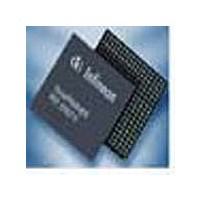
PEF22558EV11GXP Lantiq, PEF22558EV11GXP Datasheet - Page 12

PEF22558EV11GXP
Manufacturer Part Number
PEF22558EV11GXP
Description
Manufacturer
Lantiq
Datasheet
1.PEF22558EV11GXP.pdf
(90 pages)
Specifications of PEF22558EV11GXP
Screening Level
Industrial
Mounting
Surface Mount
Operating Temperature (min)
-40C
Operating Temperature (max)
85C
Lead Free Status / RoHS Status
Compliant
- Current page: 12 of 90
- Download datasheet (4Mb)
3
The microcontroller interface is selected if IM(1:0) is strapped to
´01
It is based on the existing QuadFALC
acknowledge DTACK for Motorola- and READY for Intel-mode) is provided indicating
successful read or write cycle. By using DTACK or READY respectively no counter is
necessary in the microcontroller to finish the access.
The generation of READY is asynchronous:
In Intel mode read access READY will be set to low by the OctalFALC
output is stable at the OctalFALC
micro controller), READY is low for a “hold time”, before it will be set to high by the
OctalFALC
In the Intel mode write acces READY will be set to low by the OctalFALC
falling edge of WR (which is driven by the micro controller). After WR is high and data
are written successfully into the registers of the OctalFALC
by the OctalFALC
The general timing diagrams are shown in
Figure 3
Delta Sheet
READY
B
Dx
´ (Motorola mode).
WR
CS
RD
TM
Microcontroller Interface
.
Intel Read Cycle Timing
33
TM
8
.
32
30
11
31
9
TM
. After the rising edge of RD (which is driven by the
®
interface. An additional handshake signal (data
12
Figure 3
9
to
Figure
TM
, READY will be set to high
Microcontroller Interface
7:
8
´
00
O cta l_ F AL C _ F 0 1 2 1
Rev. 2.0, 2005-05-03
B
´ (Intel mode) or
TM
OctalFALC
PEF 22558 E
after the data
TM
after the
TM
Related parts for PEF22558EV11GXP
Image
Part Number
Description
Manufacturer
Datasheet
Request
R

Part Number:
Description:
Manufacturer:
Lantiq
Datasheet:

Part Number:
Description:
Manufacturer:
Lantiq
Datasheet:

Part Number:
Description:
Manufacturer:
Lantiq
Datasheet:


