ST72T774J9B1 STMicroelectronics, ST72T774J9B1 Datasheet - Page 51
ST72T774J9B1
Manufacturer Part Number
ST72T774J9B1
Description
Manufacturer
STMicroelectronics
Datasheet
1.ST72T774J9B1.pdf
(144 pages)
Specifications of ST72T774J9B1
Cpu Family
ST7
Device Core Size
8b
Frequency (max)
24MHz
Interface Type
I2C/USB
Program Memory Type
EPROM
Program Memory Size
60KB
Total Internal Ram Size
1KB
# I/os (max)
31
Number Of Timers - General Purpose
1
Operating Supply Voltage (typ)
5V
Operating Supply Voltage (max)
5.5V
Operating Supply Voltage (min)
4V
On-chip Adc
1-chx8-bit
On-chip Dac
1-chx8-bit
Instruction Set Architecture
CISC
Operating Temp Range
0C to 70C
Operating Temperature Classification
Commercial
Mounting
Through Hole
Pin Count
42
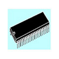
Package Type
SPDIP
Lead Free Status / Rohs Status
Specific Sites Compliant
Available stocks
Company
Part Number
Manufacturer
Quantity
Price

Part Number:
ST72T774J9B1
Manufacturer:
ST
Quantity:
20 000


4.3.4 Register Description
Each Timer is associated with three control and
status registers, and with six pairs of data registers
(16-bit values) relating to the two input captures,
the two output compares, the counter and the
alternate counter.
CONTROL REGISTER 1 (CR1)
Read/Write
Reset Value: 0000 0000 (00h)
Bit 7 = ICIE Input Capture Interrupt Enable.
Bit 6 = OCIE Output Compare Interrupt Enable.
Bit 5 = TOIE Timer Overflow Interrupt Enable.
ICIE OCIE TOIE FOLV2 FOLV1 OLVL2 IEDG1 OLVL1
7
0: Interrupt is inhibited.
1: A timer interrupt is generated whenever the
0: Interrupt is inhibited.
1: A timer interrupt is generated whenever the
0: Interrupt is inhibited.
1: A timer interrupt is enabled whenever the
ICF1 or ICF2 bit of the SR register is set.
OCF1 or OCF2 bit of the SR register is set.
TOF bit of the SR register is set.
0
Bit 4 = FOLV2 Forced Output Compare 2.
This bit is not cleared by software, only by a chip
reset.
Bit 3 = FOLV1 Forced Output Compare 1.
This bit is not cleared by software, only by a chip
reset.
Bit 2 = OLVL2 Output Level 2.
This bit is copied to the OCMP2 pin whenever a
successful comparison occurs with the OC2R
register and OCxE is set in the CR2 register. This
value is copied to the OCMP1 pin in One Pulse
Mode and Pulse Width Modulation mode.
Bit 1 = IEDG1 Input Edge 1.
This bit determines which type of level transition on
the ICAP1 pin will trigger the capture.
Bit 0 = OLVL1 Output Level 1.
The OLVL1 bit is copied to the OCMP1 pin
whenever a successful comparison occurs with
the OC1R register and the OC1E bit is set in the
CR2 register.
0: No effect.
1:Forces the OLVL2 bit to be copied to the
0: No effect.
1: Forces OLVL1 to be copied to the OCMP1
0: A falling edge triggers the capture.
1: A rising edge triggers the capture.
OCMP2 pin.
pin.
ST72774/ST727754/ST72734
51/144
Related parts for ST72T774J9B1
Image
Part Number
Description
Manufacturer
Datasheet
Request
R

Part Number:
Description:
STMicroelectronics [RIPPLE-CARRY BINARY COUNTER/DIVIDERS]
Manufacturer:
STMicroelectronics
Datasheet:
Part Number:
Description:
STMicroelectronics [LIQUID-CRYSTAL DISPLAY DRIVERS]
Manufacturer:
STMicroelectronics
Datasheet:

Part Number:
Description:
BOARD EVAL FOR MEMS SENSORS
Manufacturer:
STMicroelectronics
Datasheet:
Part Number:
Description:
NPN TRANSISTOR POWER MODULE
Manufacturer:
STMicroelectronics
Datasheet:
Part Number:
Description:
TURBOSWITCH ULTRA-FAST HIGH VOLTAGE DIODE
Manufacturer:
STMicroelectronics
Datasheet:
Part Number:
Description:
Manufacturer:
STMicroelectronics
Datasheet:
Part Number:
Description:
DIODE / SCR MODULE
Manufacturer:
STMicroelectronics
Datasheet:
Part Number:
Description:
DIODE / SCR MODULE
Manufacturer:
STMicroelectronics
Datasheet:
Part Number:
Description:
Search -----> STE16N100
Manufacturer:
STMicroelectronics
Datasheet:
Part Number:
Description:
Search ---> STE53NA50
Manufacturer:
STMicroelectronics
Datasheet:
Part Number:
Description:
NPN Transistor Power Module
Manufacturer:
STMicroelectronics
Datasheet:
Part Number:
Description:
DIODE / SCR MODULE
Manufacturer:
STMicroelectronics
Datasheet: