CP2400DK Silicon Laboratories Inc, CP2400DK Datasheet - Page 53
CP2400DK
Manufacturer Part Number
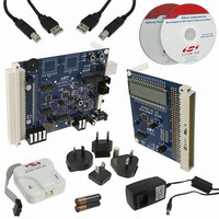
CP2400DK
Description
KIT EVAL SPI LCD DRIVER CP2400
Manufacturer
Silicon Laboratories Inc
Specifications of CP2400DK
Main Purpose
LCD Development
Embedded
Yes
Utilized Ic / Part
CP2400
Primary Attributes
I²C, SMBus Interfaces
Secondary Attributes
Up to 128 segments
Product
Microcontroller Modules
Core Processor
C8051F930
Clock Speed
20 MHz
Interface Type
SPI
Timers
2
Operating Supply Voltage
1.8 V to 3.6 V
Cpu Core
C8051F930
Lead Free Status / RoHS Status
Contains lead / RoHS non-compliant
Lead Free Status / RoHS Status
Lead free / RoHS Compliant, Contains lead / RoHS non-compliant
Other names
336-1858
336-1858
336-1858


9.5.
Shutdown mode is the lowest power mode for the CP2400/1/2/3. All device functionality is disabled in this mode
and a reset is required to wake up the device. This mode is typically used when the device is not needed for
prolonged periods of time.
From Normal Mode, the device can be placed in shutdown mode using the following procedure:
The device will not enter Shutdown if there are pending wake-up events, and the INT pin will remain asserted. To
ensure that the device has successfully entered the low power mode, the host processor should verify that there
are no pending wake-up events prior to placing the device in Shutdown Mode and that the INT pin remains de-
asserted for 100 µs after placing the device in Shutdown Mode. If the INT pin is found to be asserted after the
device has been placed in Shutdown, the device should be reset and placed in shutdown again. It is essential that
all ULP Port Mask bits be set to logic 0 before the device is placed in Shutdown in order to prevent the possibility of
a partial wake-up due to a Port Match event. The Port Match, SmaRTClock Alarm, and SmaRTClock Oscillator Fail
interrupts should always be enabled any time the device is placed in Shutdown mode.
Note: The Port I/O state and configuration settings are preserved as long as the device is in Shutdown. Upon reset, all Port I/O
state and configuration settings will reset, making all Port I/O digital inputs with weak pull-ups enabled. They will remain
in this state until the host controller re-initializes the Port I/O state and configuration registers.
Shutdown Mode
1. Set INT0EN:INT1EN to 0x1900. This enables the SmaRTClock Fail, SmaRTClock Alarm, and Port
2. Ensure that all ULP Port Mask bits are set to logic 0 by writing 1 to ULPRST (ULPCN.1).
3. Configure the bandgap for Shutdown Mode by writing 0x80 to MSCF.
4. Drive the PWR or NSS pin LOW.
5. Set the RTCDIS (ULPCN.4) and the ULPEN (ULPCN.1) bit to logic 1.
6. Drive the PWR or NSS pin HIGH.
Match interrupts and disables all others.
Rev. 1.0
CP2400/1/2/3
53
Related parts for CP2400DK
Image
Part Number
Description
Manufacturer
Datasheet
Request
R

Part Number:
Description:
IC LCD DRIVER 48TQFP
Manufacturer:
Silicon Laboratories Inc
Datasheet:
Part Number:
Description:
IC LCD DRIVER 48QFN
Manufacturer:
Silicon Laboratories Inc
Datasheet:

Part Number:
Description:
SMD/C°/SINGLE-ENDED OUTPUT SILICON OSCILLATOR
Manufacturer:
Silicon Laboratories Inc
Part Number:
Description:
Manufacturer:
Silicon Laboratories Inc
Datasheet:
Part Number:
Description:
N/A N/A/SI4010 AES KEYFOB DEMO WITH LCD RX
Manufacturer:
Silicon Laboratories Inc
Datasheet:
Part Number:
Description:
N/A N/A/SI4010 SIMPLIFIED KEY FOB DEMO WITH LED RX
Manufacturer:
Silicon Laboratories Inc
Datasheet:
Part Number:
Description:
N/A/-40 TO 85 OC/EZLINK MODULE; F930/4432 HIGH BAND (REV E/B1)
Manufacturer:
Silicon Laboratories Inc
Part Number:
Description:
EZLink Module; F930/4432 Low Band (rev e/B1)
Manufacturer:
Silicon Laboratories Inc
Part Number:
Description:
I°/4460 10 DBM RADIO TEST CARD 434 MHZ
Manufacturer:
Silicon Laboratories Inc
Part Number:
Description:
I°/4461 14 DBM RADIO TEST CARD 868 MHZ
Manufacturer:
Silicon Laboratories Inc
Part Number:
Description:
I°/4463 20 DBM RFSWITCH RADIO TEST CARD 460 MHZ
Manufacturer:
Silicon Laboratories Inc
Part Number:
Description:
I°/4463 20 DBM RADIO TEST CARD 868 MHZ
Manufacturer:
Silicon Laboratories Inc
Part Number:
Description:
I°/4463 27 DBM RADIO TEST CARD 868 MHZ
Manufacturer:
Silicon Laboratories Inc
Part Number:
Description:
I°/4463 SKYWORKS 30 DBM RADIO TEST CARD 915 MHZ
Manufacturer:
Silicon Laboratories Inc