CP2400DK Silicon Laboratories Inc, CP2400DK Datasheet - Page 56
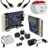
CP2400DK
Manufacturer Part Number
CP2400DK
Description
KIT EVAL SPI LCD DRIVER CP2400
Manufacturer
Silicon Laboratories Inc
Specifications of CP2400DK
Main Purpose
LCD Development
Embedded
Yes
Utilized Ic / Part
CP2400
Primary Attributes
I²C, SMBus Interfaces
Secondary Attributes
Up to 128 segments
Product
Microcontroller Modules
Core Processor
C8051F930
Clock Speed
20 MHz
Interface Type
SPI
Timers
2
Operating Supply Voltage
1.8 V to 3.6 V
Cpu Core
C8051F930
Lead Free Status / RoHS Status
Contains lead / RoHS non-compliant
Lead Free Status / RoHS Status
Lead free / RoHS Compliant, Contains lead / RoHS non-compliant
Other names
336-1858
336-1858
336-1858


CP2400/1/2/3
9.7.
The ultra low power LCD and SmaRTClock modes support port match wake-up. ULP SmaRTClock mode supports
port match on all P0, P1, P2, and P3 pins. ULP LCD mode supports port match on P3.3, P3.4, P3.5, P3.6, and
P3.7. ULP Port Match events can be generated on rising or falling edges; however, all events are configured to the
same polarity using the ULPPMPOL bit (ULPCN.0). ULP Port Match is level sensitive and a new Port Match event
will be generated every clock cycle as long as the I/O state matches the polarity set by the ULPPMPOL bit.
Note: In ULP LCD Mode, when using a 4-mux LCD, port match may only be used to detect rising edges.
Each Port I/O that participates in ULP Port Match is individually maskable to allow or disallow the generation of
Port Match events. The most significant bit in each 4-bit nibble of ULP Memory controls the masking of a single
Port I/O. For example, the masking of P3.4 and P3.5 are controlled by bit 3 and bit 7 of ULPMEM14, respectively.
Table 9.1 and Table 9.2 show the ULP Mask bit locations for all I/O capable of port match when the device is in
ULP SmaRTClock and ULP LCD mode, respectively. A mask setting of 0 will prevent the generation of Port Match
events from the specified I/O and a mask setting of 1 will allow generation of Port Match events from the specified
I/O. Port I/O to be used for ULP Port Match must be configured as digital pins. Setting the ULPRST (ULPCN.1) to
logic 1 will reset all Port Mask bits to 0.
ULP Port Match is enabled upon entry into ULP mode when the ULPEN bit (ULPCN.1) is set to logic 1 and
disabled upon wake-up from ULP mode. The ULPST register may be used to determine when a ULP Port Match
event has occurred. When enabled, the Port Match interrupt will occur when an Active Mode Port Match or ULP
Port Match event occurs.
56
Port Match Functionality in the Ultra Low Power Modes
ULP Memory
ULP Memory
ULPMEM00
ULPMEM01
ULPMEM02
ULPMEM03
ULPMEM04
ULPMEM05
ULPMEM06
ULPMEM07
ULPMEM08
ULPMEM09
ULPMEM10
ULPMEM12
ULPMEM13
ULPMEM14
ULPMEM15
ULPMEM13
ULPMEM14
ULPMEM15
ULPMEM11
Table 9.1. ULP SmaRTClock Port Match Mask Bit Locations
Table 9.2. ULP LCD Port Match Mask Bit Locations
Rev. 1.0
Bit 7 Masks
Bit 7 Masks
P0.1
P0.3
P0.5
P0.7
P1.1
P1.3
P1.5
P1.7
P2.1
P2.3
P2.5
P2.7
P3.1
P3.3
P3.5
P3.7
P3.3
P3.5
P3.7
Bit 3 Masks
Bit 3 Masks
P0.0
P0.2
P0.4
P0.6
P1.0
P1.2
P1.4
P1.6
P2.0
P2.2
P2.4
P2.6
P3.0
P3.2
P3.4
P3.6
P3.4
P3.6
N/A
Related parts for CP2400DK
Image
Part Number
Description
Manufacturer
Datasheet
Request
R

Part Number:
Description:
IC LCD DRIVER 48TQFP
Manufacturer:
Silicon Laboratories Inc
Datasheet:
Part Number:
Description:
IC LCD DRIVER 48QFN
Manufacturer:
Silicon Laboratories Inc
Datasheet:

Part Number:
Description:
SMD/C°/SINGLE-ENDED OUTPUT SILICON OSCILLATOR
Manufacturer:
Silicon Laboratories Inc
Part Number:
Description:
Manufacturer:
Silicon Laboratories Inc
Datasheet:
Part Number:
Description:
N/A N/A/SI4010 AES KEYFOB DEMO WITH LCD RX
Manufacturer:
Silicon Laboratories Inc
Datasheet:
Part Number:
Description:
N/A N/A/SI4010 SIMPLIFIED KEY FOB DEMO WITH LED RX
Manufacturer:
Silicon Laboratories Inc
Datasheet:
Part Number:
Description:
N/A/-40 TO 85 OC/EZLINK MODULE; F930/4432 HIGH BAND (REV E/B1)
Manufacturer:
Silicon Laboratories Inc
Part Number:
Description:
EZLink Module; F930/4432 Low Band (rev e/B1)
Manufacturer:
Silicon Laboratories Inc
Part Number:
Description:
I°/4460 10 DBM RADIO TEST CARD 434 MHZ
Manufacturer:
Silicon Laboratories Inc
Part Number:
Description:
I°/4461 14 DBM RADIO TEST CARD 868 MHZ
Manufacturer:
Silicon Laboratories Inc
Part Number:
Description:
I°/4463 20 DBM RFSWITCH RADIO TEST CARD 460 MHZ
Manufacturer:
Silicon Laboratories Inc
Part Number:
Description:
I°/4463 20 DBM RADIO TEST CARD 868 MHZ
Manufacturer:
Silicon Laboratories Inc
Part Number:
Description:
I°/4463 27 DBM RADIO TEST CARD 868 MHZ
Manufacturer:
Silicon Laboratories Inc
Part Number:
Description:
I°/4463 SKYWORKS 30 DBM RADIO TEST CARD 915 MHZ
Manufacturer:
Silicon Laboratories Inc