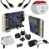
CP2400DK Silicon Laboratories Inc, CP2400DK Datasheet - Page 83

CP2400DK
Manufacturer Part Number
CP2400DK
Description
KIT EVAL SPI LCD DRIVER CP2400
Manufacturer
Silicon Laboratories Inc
Specifications of CP2400DK
Main Purpose
LCD Development
Embedded
Yes
Utilized Ic / Part
CP2400
Primary Attributes
I²C, SMBus Interfaces
Secondary Attributes
Up to 128 segments
Product
Microcontroller Modules
Core Processor
C8051F930
Clock Speed
20 MHz
Interface Type
SPI
Timers
2
Operating Supply Voltage
1.8 V to 3.6 V
Cpu Core
C8051F930
Lead Free Status / RoHS Status
Contains lead / RoHS non-compliant
Lead Free Status / RoHS Status
Lead free / RoHS Compliant, Contains lead / RoHS non-compliant
Other names
336-1858
336-1858
336-1858
12. LCD Segment Driver
CP2400/1/2/3 devices contain an LCD segment driver and on-chip bias generation that supports static, 2-mux, 3-
mux and 4-mux LCDs with 1/2 or 1/3 bias. The on-chip charge pump with programmable output voltage allows
software contrast control which is independent of the VDD supply voltage. LCD timing is derived from the
SmaRTClock oscillator to allow precise control over the refresh rate. A low frequency clock present on the CLK pin
may also be used as the LCD clock source.
The CP2400/1/2/3 contains on-chip ULP memory to store the enabled/disabled state of individual LCD segments.
All LCD waveforms are generated on-chip and software only needs to access the ULP memory to change the
information displayed on the LCD. An LCD blinking function is also supported. A block diagram of the LCD
segment driver is shown in Figure 12.1.
12.1. Initializing the LCD Segment Driver
The following procedure is recommended for using the LCD Segment Driver:
XTAL1
XTAL2
CLK
1. Configure the LCD size, mux mode, and bias using the LCD0CN register.
2. Configure the Port I/O pins to be used for LCD as Analog I/O.
3. Set the LCD contrast using the CONTRAST register.
4. Write the reserved value of 0x9F to LCD0CF.
5. Set the LCD refresh rate using the LCD0DIVH:LCD0DIVL registers.
6. Set the LCD toggle rate using the LCD0TOGR register.
7. Set the LCD power mode using the LCD0PWR register.
8. Write a pattern to the ULP memory.
9. Enable the LCD using the master control (MSCN) register.
SmaRTClock
Figure 12.1. LCD Segment Driver Block Diagram
RTCBYP
Charge
VDD
Pump
Configuration
Registers
Rev. 1.0
CPBYP
LCD State Machine
CAP
ULP Memory
10 uF
Generator
LCD Segment Driver
Bias
CP2400/1/2/3
Drivers
Port
4 COM Pins
Segment
Pins
83


