STEVAL-IFW001V1 STMicroelectronics, STEVAL-IFW001V1 Datasheet - Page 33
STEVAL-IFW001V1
Manufacturer Part Number
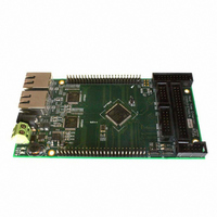
STEVAL-IFW001V1
Description
BOARD EVAL BASED ON STR912FA
Manufacturer
STMicroelectronics
Datasheets
1.STEVAL-IFW001V1.pdf
(102 pages)
2.STEVAL-IFW001V1.pdf
(9 pages)
3.STEVAL-IFW001V1.pdf
(7 pages)
Specifications of STEVAL-IFW001V1
Design Resources
STEVAL-IFW001V1 Gerber Files STEVAL-IFW001V1 Schematic STEVAL-IFW001V1 Bill of Material
Main Purpose
Interface, Ethernet
Embedded
Yes, MCU, 32-Bit
Utilized Ic / Part
E-STE101P, STR912FAW44
Primary Attributes
Dual Ethernet Transceivers for Full Duplex Communication
Secondary Attributes
Up to 32 MII Addresses, UART, I2C, SPI, with RJ45 Connectors
Silicon Manufacturer
ST Micro
Core Architecture
ARM
Core Sub-architecture
ARM9
Silicon Core Number
STR9
Silicon Family Name
STR91x
For Use With
497-8263 - BOARD EXTENSION STEVAL-IFW001V1
Lead Free Status / RoHS Status
Lead free / RoHS Compliant
Other names
497-8262


STR91xFAxxx
3.20
3.20.1
3.21
UART interfaces with DMA
The STR91xFA supports three independent UART serial interfaces, designated UART0,
UART1, and UART2. Each interface is very similar to the industry-standard 16C550 UART
device. All three UART channels support IrDA encoding/decoding, requiring only an external
LED transceiver to pins UARTx_RX and UARTx_Tx for communication. One UART channel
(UART0) supports full modem control signals.
UART interfaces include the following features:
●
●
●
●
●
●
●
●
●
●
●
For your reference, only two standard 16550 UART features are not supported, 1.5 stop bits
and independent receive clock.
DMA
A programmable DMA channel may be assigned by CPU firmware to service channels
UART0 and UART1 for fast and direct transfers between the UART bus and SRAM with little
CPU involvement. Both DMA single-transfers and DMA burst-transfers are supported for
transmit and receive. Burst transfers require that UART FIFOs are enabled.
I
The STR91xFA supports two independent I2C serial interfaces, designated I2C0, and I2C1.
Each interface allows direct connection to an I2C bus as either a bus master or bus slave
device (firmware configurable). I2C is a two-wire communication channel, having a bi-
directional data signal and a single-directional clock signal based on open-drain line drivers,
requiring external pull-up resistors.
Byte-wide data is transferred between a Master device and a Slave device on two wires.
More than one bus Master is allowed, but only one Master may control the bus at any given
time. Data is not lost when another Master requests the use of a busy bus because I2C
supports collision detection and arbitration. More than one Slave device may be present on
the bus, each having a unique address. The bus Master initiates all data movement and
generates the clock that permits the transfer. Once a transfer is initiated by the Master, any
device that is addressed is considered a Slave. Automatic clock synchronization allows I2C
devices with different bit rates to communicate on the same physical bus.
2
C interfaces
Maximum baud rate of 1.5 Mbps
Separate FIFOs for transmit and receive, each 16 deep, each FIFO can be disabled by
firmware if desired
Programmable FIFO trigger levels between 1/8 and 7/8
Programmable baud rate generator based on CCU master clock, or CCU master clock
divided by two
Programmable serial data lengths of 5, 6, 7, or 8 bits with start bit and 1 or 2 stop bits
Programmable selection of even, odd, or no-parity bit generation and detection
False start-bit detection
Line break generation and detection
Support of IrDA SIR ENDEC functions for data rates of up to 115.2K bps
IrDA bit duration selection of 3/16 or low-power (1.14 to 2.23 µsec)
Channel UART0 supports modem control functions CTS, DCD, DSR, RTS, DTR, and
RI
Doc ID 13495 Rev 6
Functional overview
33/102
Related parts for STEVAL-IFW001V1
Image
Part Number
Description
Manufacturer
Datasheet
Request
R

Part Number:
Description:
BOARD EVAL SPZB260 MOD FOR STR9
Manufacturer:
STMicroelectronics
Datasheet:

Part Number:
Description:
BOARD EVAL EXTENSION SN250
Manufacturer:
STMicroelectronics
Datasheet:

Part Number:
Description:
BOARD EVAL AB-54003L-512
Manufacturer:
STMicroelectronics
Datasheet:

Part Number:
Description:
BOARD REF DESIGN RF DMOS PWR AMP
Manufacturer:
STMicroelectronics
Datasheet:

Part Number:
Description:
BOARD EVAL PWR AMP AB-84008L-470
Manufacturer:
STMicroelectronics
Datasheet:

Part Number:
Description:
BOARD EVAL FOR STM32F103XX
Manufacturer:
STMicroelectronics
Datasheet:

Part Number:
Description:
BOARD EVAL AB-54003L-512
Manufacturer:
STMicroelectronics
Datasheet:

Part Number:
Description:
BOARD SMART PLUG STM32 SPZB260PR
Manufacturer:
STMicroelectronics
Datasheet:

Part Number:
Description:
BOARD DEMO BLUETOOTH SPBT2532C2
Manufacturer:
STMicroelectronics
Datasheet:
Part Number:
Description:
ZIGBEE USB DONGLE EVAL KIT
Manufacturer:
STMicroelectronics
Datasheet:
Part Number:
Description:
STMicroelectronics [RIPPLE-CARRY BINARY COUNTER/DIVIDERS]
Manufacturer:
STMicroelectronics
Datasheet:
Part Number:
Description:
STMicroelectronics [LIQUID-CRYSTAL DISPLAY DRIVERS]
Manufacturer:
STMicroelectronics
Datasheet:

Part Number:
Description:
BOARD EVAL FOR MEMS SENSORS
Manufacturer:
STMicroelectronics
Datasheet: