OM11014 NXP Semiconductors, OM11014 Datasheet - Page 3
OM11014
Manufacturer Part Number
OM11014
Description
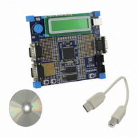
BOARD EVAL FOR LPC2919
Manufacturer
NXP Semiconductors
Series
Keilr
Type
MCUr
Datasheet
1.OM11014.pdf
(67 pages)
Specifications of OM11014
Contents
Board, Cable, CD
For Use With/related Products
LPC2919
Lead Free Status / RoHS Status
Not applicable / Not applicable
Other names
568-4360


NXP Semiconductors
3. Features
LPC2917_19_1
Product data sheet
2.4 On-chip static RAM
3.1 General
In addition to the two 16 kB TCMs the LPC2917/19 includes two static RAM memories:
one of 32 kB and one of 16 kB. Both may be used for code and/or data storage.
I
I
I
I
I
I
I
I
I
I
I
I
I
I
I
I
I
I
I
ARM968E-S processor at 80 MHz maximum.
AHB system bus at 80 MHz.
On-chip memory:
Two-channel CAN controller supporting Full-CAN and extensive message filtering.
Two LIN master controllers with full hardware support for LIN communication.
Two 550 UARTs with 16-byte TX and RX FIFO depths.
Three full-duplex queued SPIs with four slave-select lines; 16 bits wide; 8 locations
deep; TX FIFO and RX FIFO.
Four 32-bit timers each containing four capture-and-compare registers linked to I/Os.
Four 6-channel PWMs with capture and trap functionality.
32-bit watchdog with timer change protection, running on safe clock.
Up to 108 general-purpose I/O pins with programmable pull-up, pull-down or bus
keeper.
Vectored Interrupt Controller (VIC) with 16 priority levels.
Two 8-channel 10-bit ADCs provide a total of up to 16 analog inputs, with conversion
times as low as 2.44 s per channel. Each channel provides a compare function to
minimize interrupts.
Up to 24 level-sensitive external interrupt pins, including CAN and LIN wake-up
features.
External Static Memory Controller (SMC) with eight memory banks; up to 32-bit data
bus; up to 24-bit address bus.
Processor wake-up from power-down via external interrupt pins; CAN or LIN activity.
Flexible Reset Generation Unit (RGU) able to control resets of individual modules.
Flexible Clock Generation Unit (CGU) able to control clock frequency of individual
modules:
Highly configurable system Power Management Unit (PMU):
N
N
N
N
N
N
N
N
N
Two Tightly Coupled Memories (TCM), 16 kB Instruction TCM (ITCM), 16 kB Data
TCM (DTCM).
Two separate internal SRAM instances; 32 kB and 16 kB.
Up to 768 kB flash program memory.
On-chip very low-power ring oscillator; fixed frequency of 0.4 MHz; always on to
provide a Safe_Clock source for system monitoring.
On-chip crystal oscillator with a recommended operating range from 10 MHz to
25 MHz - maximum PLL input 15 MHz.
On-chip PLL allows CPU operation up to a maximum CPU rate of 80 MHz.
Generation of up to 10 base clocks.
Seven fractional dividers.
Clock control of individual modules.
Rev. 01 — 31 July 2008
ARM9 microcontroller with CAN and LIN
LPC2917/19
© NXP B.V. 2008. All rights reserved.
3 of 67
Related parts for OM11014
Image
Part Number
Description
Manufacturer
Datasheet
Request
R

Part Number:
Description:
NXP Semiconductors designed the LPC2420/2460 microcontroller around a 16-bit/32-bitARM7TDMI-S CPU core with real-time debug interfaces that include both JTAG andembedded trace
Manufacturer:
NXP Semiconductors
Datasheet:

Part Number:
Description:
NXP Semiconductors designed the LPC2458 microcontroller around a 16-bit/32-bitARM7TDMI-S CPU core with real-time debug interfaces that include both JTAG andembedded trace
Manufacturer:
NXP Semiconductors
Datasheet:
Part Number:
Description:
NXP Semiconductors designed the LPC2468 microcontroller around a 16-bit/32-bitARM7TDMI-S CPU core with real-time debug interfaces that include both JTAG andembedded trace
Manufacturer:
NXP Semiconductors
Datasheet:
Part Number:
Description:
NXP Semiconductors designed the LPC2470 microcontroller, powered by theARM7TDMI-S core, to be a highly integrated microcontroller for a wide range ofapplications that require advanced communications and high quality graphic displays
Manufacturer:
NXP Semiconductors
Datasheet:
Part Number:
Description:
NXP Semiconductors designed the LPC2478 microcontroller, powered by theARM7TDMI-S core, to be a highly integrated microcontroller for a wide range ofapplications that require advanced communications and high quality graphic displays
Manufacturer:
NXP Semiconductors
Datasheet:
Part Number:
Description:
The Philips Semiconductors XA (eXtended Architecture) family of 16-bit single-chip microcontrollers is powerful enough to easily handle the requirements of high performance embedded applications, yet inexpensive enough to compete in the market for hi
Manufacturer:
NXP Semiconductors
Datasheet:
Part Number:
Description:
The XA-S3 device is a member of Philips Semiconductors? XA(eXtended Architecture) family of high performance 16-bitsingle-chip microcontrollers
Manufacturer:
NXP Semiconductors
Datasheet:

Part Number:
Description:
The NXP BlueStreak LH75401/LH75411 family consists of two low-cost 16/32-bit System-on-Chip (SoC) devices
Manufacturer:
NXP Semiconductors
Datasheet:
Part Number:
Description:
The NXP LPC3130/3131 combine an 180 MHz ARM926EJ-S CPU core, high-speed USB2
Manufacturer:
NXP Semiconductors
Datasheet:
Part Number:
Description:
The NXP LPC3141 combine a 270 MHz ARM926EJ-S CPU core, High-speed USB 2
Manufacturer:
NXP Semiconductors
Part Number:
Description:
The NXP LPC3143 combine a 270 MHz ARM926EJ-S CPU core, High-speed USB 2
Manufacturer:
NXP Semiconductors

Part Number:
Description:
The NXP LPC3152 combines an 180 MHz ARM926EJ-S CPU core, High-speed USB 2
Manufacturer:
NXP Semiconductors
Part Number:
Description:
The NXP LPC3154 combines an 180 MHz ARM926EJ-S CPU core, High-speed USB 2
Manufacturer:
NXP Semiconductors

Part Number:
Description:
Standard level N-channel enhancement mode Field-Effect Transistor (FET) in a plastic package using NXP High-Performance Automotive (HPA) TrenchMOS technology
Manufacturer:
NXP Semiconductors
Datasheet: