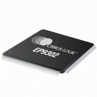
EP9302-CQZ Cirrus Logic Inc, EP9302-CQZ Datasheet - Page 186

EP9302-CQZ
Manufacturer Part Number
EP9302-CQZ
Description
IC ARM9 SOC PROCESSOR 208LQFP
Manufacturer
Cirrus Logic Inc
Series
EP9r
Datasheets
1.EP9307-CRZ.pdf
(824 pages)
2.EP9302-IQZ.pdf
(42 pages)
3.EP9302-IQZ.pdf
(4 pages)
4.EP9302-IQZ.pdf
(40 pages)
Specifications of EP9302-CQZ
Program Memory Type
ROMless
Package / Case
208-LQFP
Core Processor
ARM9
Core Size
16/32-Bit
Speed
200MHz
Connectivity
EBI/EMI, Ethernet, I²C, IrDA, SPI, UART/USART, USB
Peripherals
AC'97, DMA, I²:S, LED, MaverickKey, POR, PWM, WDT
Number Of I /o
19
Ram Size
32K x 8
Voltage - Supply (vcc/vdd)
1.65 V ~ 3.6 V
Data Converters
A/D 5x12b
Oscillator Type
External
Operating Temperature
0°C ~ 70°C
Processor Series
EP93xx
Core
ARM920T
Data Bus Width
32 bit
Data Ram Size
16 bit
Interface Type
USB, USART, SPI
Maximum Clock Frequency
200 MHz
Number Of Programmable I/os
37
Mounting Style
SMD/SMT
3rd Party Development Tools
MDK-ARM, RL-ARM, ULINK2
Development Tools By Supplier
EDB9302A-Z
Controller Family/series
(ARM9)
No. Of I/o's
19
Ram Memory Size
16MB
Cpu Speed
200MHz
No. Of Timers
4
Embedded Interface Type
AC97, I2S, SPI, UART, USB
Rohs Compliant
Yes
Lead Free Status / RoHS Status
Lead free / RoHS Compliant
For Use With
598-1132 - KIT DEVELOPMENT EP9302 ARM9
Eeprom Size
-
Program Memory Size
-
Lead Free Status / Rohs Status
Lead free / RoHS Compliant
Other names
598-1137
Available stocks
Company
Part Number
Manufacturer
Quantity
Price
Company:
Part Number:
EP9302-CQZ
Manufacturer:
Cirrus
Quantity:
3 295
Company:
Part Number:
EP9302-CQZ
Manufacturer:
ALTERA
Quantity:
672
Part Number:
EP9302-CQZ
Manufacturer:
CYPRESS/赛普拉斯
Quantity:
20 000
- EP9307-CRZ PDF datasheet
- EP9302-IQZ PDF datasheet #2
- EP9302-IQZ PDF datasheet #3
- EP9302-IQZ PDF datasheet #4
- Current page: 186 of 824
- Download datasheet (13Mb)
7
7-4
Raster Engine With Analog/LCD Integrated Timing and Interface
EP93xx User’s Guide
7.3.2 Color Look-Up Tables
7.3.3 Grayscale/Color Generation for Monochrome/Passive Low Color
7.3.4 Frame Buffer Organization
to one pixel combination blinking. For 16 bpp and 24 bpp modes, the LUT blink circuitry is
usually bypassed and the blink functions are logic transformations of the pixel data. In
addition to logical AND/OR/XOR LUT address translations, the circuitry will support logical
blink to background, blink dim, blink bright, and blink to reverse.
The raster engine block contains dual color pixel LUTs (Look-Up-Tables). Each LUT will allow
the engine to output 256 different pixel combinations of 24-bit pixels in lower color depth
modes.
The video pipeline includes circuitry that can be configured to provide grayscale or color
generation for generating grayscales on monochrome displays or adding color depth on low
color LCD displays, respectively. For monochrome displays, the circuitry supports up to 8
grayscale shades including on and off. For low color LCD displays, the circuitry supports up
to 512 colors. The circuitry does this by rapidly turning on and off (dithering) pixels based on
frame count, screen location, and pixel value. For grayscale displays, the pixel gray
appearance is determined by 3 bits of the pixel data. For color depth expansion on LCD
displays, the pixel color appearance is determined by 3 bits each from the red, green, and
blue portions of the pixel data.
The Raster Engine is designed to support video information as DIB (Device Independent
Bitmap) format stored in a packed pixel architecture. However, the engine does not require
that video information be stored in a packed line architecture. The circuitry allows a different
memory organization between video scan out and graphic image memory. Therefore,
memory gaps can exist between lines. This means that the graphics memory may be
organized wider than the video frame. This type of feature could be used for left and right
panning of the displayed information. The video frame buffer can be located in main memory,
or in a dedicated video frame area. The beginning of video lines can be located on any word
boundary. This architecture allows efficient use of memory regardless of the active video line
length. Video screen start registers determine the upper left corner of the video screen. Video
word addressing in screen memory is from left to right and then from top to bottom. Four-bit
pixels packed within video words are organized in DIB format with the left most pixel in the
Displays
Copyright 2007 Cirrus Logic
DS785UM1
Related parts for EP9302-CQZ
Image
Part Number
Description
Manufacturer
Datasheet
Request
R

Part Number:
Description:
IC ARM9 SOC PROCESSOR 208LQFP
Manufacturer:
Cirrus Logic Inc
Datasheet:

Part Number:
Description:
High Performance, Entry Level ARM9 SoC
Manufacturer:
Cirrus Logic Inc

Part Number:
Description:
MCU, MPU & DSP Development Tools Eval Bd Hgh-Prfrmnc ARM9 SOC Processor
Manufacturer:
Cirrus Logic Inc
Datasheet:

Part Number:
Description:
Development Kit
Manufacturer:
Cirrus Logic Inc
Datasheet:

Part Number:
Description:
Development Kit
Manufacturer:
Cirrus Logic Inc
Datasheet:

Part Number:
Description:
High-efficiency PFC + Fluorescent Lamp Driver Reference Design
Manufacturer:
Cirrus Logic Inc
Datasheet:

Part Number:
Description:
Development Kit
Manufacturer:
Cirrus Logic Inc
Datasheet:

Part Number:
Description:
Development Kit
Manufacturer:
Cirrus Logic Inc
Datasheet:

Part Number:
Description:
Development Kit
Manufacturer:
Cirrus Logic Inc
Datasheet:

Part Number:
Description:
Development Kit
Manufacturer:
Cirrus Logic Inc
Datasheet:

Part Number:
Description:
Development Kit
Manufacturer:
Cirrus Logic Inc
Datasheet:

Part Number:
Description:
Ref Bd For Speakerbar MSA & DSP Products
Manufacturer:
Cirrus Logic Inc


