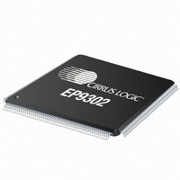
EP9302-CQZ Cirrus Logic Inc, EP9302-CQZ Datasheet - Page 663

EP9302-CQZ
Manufacturer Part Number
EP9302-CQZ
Description
IC ARM9 SOC PROCESSOR 208LQFP
Manufacturer
Cirrus Logic Inc
Series
EP9r
Datasheets
1.EP9307-CRZ.pdf
(824 pages)
2.EP9302-IQZ.pdf
(42 pages)
3.EP9302-IQZ.pdf
(4 pages)
4.EP9302-IQZ.pdf
(40 pages)
Specifications of EP9302-CQZ
Program Memory Type
ROMless
Package / Case
208-LQFP
Core Processor
ARM9
Core Size
16/32-Bit
Speed
200MHz
Connectivity
EBI/EMI, Ethernet, I²C, IrDA, SPI, UART/USART, USB
Peripherals
AC'97, DMA, I²:S, LED, MaverickKey, POR, PWM, WDT
Number Of I /o
19
Ram Size
32K x 8
Voltage - Supply (vcc/vdd)
1.65 V ~ 3.6 V
Data Converters
A/D 5x12b
Oscillator Type
External
Operating Temperature
0°C ~ 70°C
Processor Series
EP93xx
Core
ARM920T
Data Bus Width
32 bit
Data Ram Size
16 bit
Interface Type
USB, USART, SPI
Maximum Clock Frequency
200 MHz
Number Of Programmable I/os
37
Mounting Style
SMD/SMT
3rd Party Development Tools
MDK-ARM, RL-ARM, ULINK2
Development Tools By Supplier
EDB9302A-Z
Controller Family/series
(ARM9)
No. Of I/o's
19
Ram Memory Size
16MB
Cpu Speed
200MHz
No. Of Timers
4
Embedded Interface Type
AC97, I2S, SPI, UART, USB
Rohs Compliant
Yes
Lead Free Status / RoHS Status
Lead free / RoHS Compliant
For Use With
598-1132 - KIT DEVELOPMENT EP9302 ARM9
Eeprom Size
-
Program Memory Size
-
Lead Free Status / Rohs Status
Lead free / RoHS Compliant
Other names
598-1137
Available stocks
Company
Part Number
Manufacturer
Quantity
Price
Company:
Part Number:
EP9302-CQZ
Manufacturer:
Cirrus
Quantity:
3 295
Company:
Part Number:
EP9302-CQZ
Manufacturer:
ALTERA
Quantity:
672
Part Number:
EP9302-CQZ
Manufacturer:
CYPRESS/赛普拉斯
Quantity:
20 000
- EP9307-CRZ PDF datasheet
- EP9302-IQZ PDF datasheet #2
- EP9302-IQZ PDF datasheet #3
- EP9302-IQZ PDF datasheet #4
- Current page: 663 of 824
- Download datasheet (13Mb)
DS785UM1
21.4 I
The following information is required to generate a set of clocks for the I
port i2s_mstr_clk_cfg is used to supply the Syscon block the necessary control information in
2
S Master Clock Generation
Descriptions” on page 448.) Note that both left and right sample registers must be read
for the I
were last read from the FIFO will be put onto the APB bus. The FIFO read pointer is not
updated and stays pointing to the same location. The FIFO underflow flag in the Global
Control Status register is asserted. (See “Register Descriptions” on page 448.) If this
happens to be the first attempted read by the programmer on the FIFO while the FIFO
is still empty, the contents at FIFO location 0 are put onto the APB bus. These contents
are zero if the I
received and the FIFO is full, the new samples are ignored. The existing contents in
FIFO locations 0 to 7 are not touched. An internal Overflow bit is set, marking the FIFO
pointer location at which the last good data was received (that is, at [current FIFO
pointer location - 1]). When the FIFO pointer eventually points at this location again,
after reading all 7 other FIFO locations, the FIFO overflow flag in the Global Control
Status Register is asserted (and an interrupt is asserted, if enabled). The Status
Register bit (and interrupt) is cleared by reading a left / right stereo sample pair from this
FIFO location.
upper bits will be set to zero by the I
registers. Once the new configuration has been set, the channels can be re-enabled
following the specified start order.
has 5 bits per FIFO that reflect the state of the FIFO. They are:
If the programmer attempts to read from the FIFO while it is empty, the contents that
If the I
The data in the FIFO’s is always right justified for word lengths of 16 and 24 bits. The
The I
The status of each FIFO is reflected in the Global Control Status register. This register
• Rx0_underflow - Gets set when the programmer reads the FIFO when it is empty.
• Rx0_overflow - Gets set when an Rx overflow has occurred, and the FIFO pointer is
• Rx0_fifo_empty - Gets set when there are no left and right stereo samples in the
• Rx0_fifo_half_full - Gets set when there are 4 left and right stereo samples or less in
• Rx0_fifo_full - Gets set when there are 8 left and right stereo samples in the FIFO.
pointing at the last FIFO location where data was received before the overflow
occurred
FIFO.
the FIFO.
2
S transmit and receive channels should be disabled before modifying the control
2
S controller signals to the FIFO that new stereo sample pairs have been
2
S controller to consider the location to be free and modify the internal counter.
2
S controller has been reset previously.
Copyright 2007 Cirrus Logic
2
S controller in this case.
2
S controller. The I
EP93xx User’s Guide
I
2
S Controller
21-7
2
S
21
Related parts for EP9302-CQZ
Image
Part Number
Description
Manufacturer
Datasheet
Request
R

Part Number:
Description:
IC ARM9 SOC PROCESSOR 208LQFP
Manufacturer:
Cirrus Logic Inc
Datasheet:

Part Number:
Description:
High Performance, Entry Level ARM9 SoC
Manufacturer:
Cirrus Logic Inc

Part Number:
Description:
MCU, MPU & DSP Development Tools Eval Bd Hgh-Prfrmnc ARM9 SOC Processor
Manufacturer:
Cirrus Logic Inc
Datasheet:

Part Number:
Description:
Development Kit
Manufacturer:
Cirrus Logic Inc
Datasheet:

Part Number:
Description:
Development Kit
Manufacturer:
Cirrus Logic Inc
Datasheet:

Part Number:
Description:
High-efficiency PFC + Fluorescent Lamp Driver Reference Design
Manufacturer:
Cirrus Logic Inc
Datasheet:

Part Number:
Description:
Development Kit
Manufacturer:
Cirrus Logic Inc
Datasheet:

Part Number:
Description:
Development Kit
Manufacturer:
Cirrus Logic Inc
Datasheet:

Part Number:
Description:
Development Kit
Manufacturer:
Cirrus Logic Inc
Datasheet:

Part Number:
Description:
Development Kit
Manufacturer:
Cirrus Logic Inc
Datasheet:

Part Number:
Description:
Development Kit
Manufacturer:
Cirrus Logic Inc
Datasheet:

Part Number:
Description:
Ref Bd For Speakerbar MSA & DSP Products
Manufacturer:
Cirrus Logic Inc


