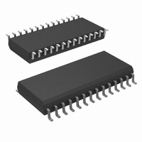
COP8SGR728M7/NOPB National Semiconductor, COP8SGR728M7/NOPB Datasheet - Page 15

COP8SGR728M7/NOPB
Manufacturer Part Number
COP8SGR728M7/NOPB
Description
MCU 8BIT CMOS ROM OTP 28-SOIC
Manufacturer
National Semiconductor
Series
COP8™ 8SGr
Datasheet
1.COP8SGE728N8NOPB.pdf
(62 pages)
Specifications of COP8SGR728M7/NOPB
Core Processor
COP8
Core Size
8-Bit
Speed
15MHz
Connectivity
Microwire/Plus (SPI), UART/USART
Peripherals
POR, PWM, WDT
Number Of I /o
24
Program Memory Size
32KB (32K x 8)
Program Memory Type
OTP
Ram Size
512 x 8
Voltage - Supply (vcc/vdd)
2.7 V ~ 5.5 V
Oscillator Type
Internal
Operating Temperature
-40°C ~ 125°C
Package / Case
28-SOIC
Data Bus Width
8 bit
Maximum Clock Frequency
15 MHz
Data Ram Size
512 B
Number Of Programmable I/os
40
Number Of Timers
3
Height
2.34 mm
Interface Type
USART
Length
17.91 mm
Maximum Operating Temperature
+ 125 C
Minimum Operating Temperature
- 40 C
Supply Voltage (max)
5.5 V
Supply Voltage (min)
2.7 V
Width
7.49 mm
For Use With
COP8SG-EPU - BOARD PROTOTYPE/TARGET COP8
Lead Free Status / RoHS Status
Lead free / RoHS Compliant
Eeprom Size
-
Data Converters
-
Lead Free Status / Rohs Status
Details
Other names
COP8SGR728M7
4.0 Pin Descriptions
Note: For compatibility with existing software written for COP888xG devices
Port D is an 8-bit output port that is preset high when RESET
goes low. The user can tie two or more D port outputs
(except D2) together in order to get a higher drive.
Note: Care must be exercised with the D2 pin operation. At RESET, the
and with existing Mask ROM devices, a read of the Port I input pins
(address xxD7) will return the same data as reading the Port F input
pins (address xx96). It is recommended new applications which will go
to production with the COP8SGx use the Port F addresses. Note that
compatible ROM devices contains the input only Port I instead of the
bi-directional Port F.
external loads on this pin must ensure that the output voltages stay
above 0.7 V
keep the external loading on D2 to less than 1000 pF.
FIGURE 4. I/O Port Configurations
CC
to prevent the chip from entering special modes. Also
(Continued)
10131710
15
FIGURE 5. I/O Port Configurations — Output Mode
FIGURE 6. I/O Port Configurations — Input Mode
www.national.com
10131711
10131712


