COP8SGR728M7/NOPB National Semiconductor, COP8SGR728M7/NOPB Datasheet - Page 26
COP8SGR728M7/NOPB
Manufacturer Part Number
COP8SGR728M7/NOPB
Description
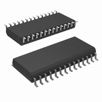
MCU 8BIT CMOS ROM OTP 28-SOIC
Manufacturer
National Semiconductor
Series
COP8™ 8SGr
Datasheet
1.COP8SGE728N8NOPB.pdf
(62 pages)
Specifications of COP8SGR728M7/NOPB
Core Processor
COP8
Core Size
8-Bit
Speed
15MHz
Connectivity
Microwire/Plus (SPI), UART/USART
Peripherals
POR, PWM, WDT
Number Of I /o
24
Program Memory Size
32KB (32K x 8)
Program Memory Type
OTP
Ram Size
512 x 8
Voltage - Supply (vcc/vdd)
2.7 V ~ 5.5 V
Oscillator Type
Internal
Operating Temperature
-40°C ~ 125°C
Package / Case
28-SOIC
Data Bus Width
8 bit
Maximum Clock Frequency
15 MHz
Data Ram Size
512 B
Number Of Programmable I/os
40
Number Of Timers
3
Height
2.34 mm
Interface Type
USART
Length
17.91 mm
Maximum Operating Temperature
+ 125 C
Minimum Operating Temperature
- 40 C
Supply Voltage (max)
5.5 V
Supply Voltage (min)
2.7 V
Width
7.49 mm
For Use With
COP8SG-EPU - BOARD PROTOTYPE/TARGET COP8
Lead Free Status / RoHS Status
Lead free / RoHS Compliant
Eeprom Size
-
Data Converters
-
Lead Free Status / Rohs Status
Details
Other names
COP8SGR728M7


www.national.com
7.0 Power Saving Features
7.2 IDLE MODE
The device is placed in the IDLE mode by writing a “1” to the
IDLE flag (G6 data bit). In this mode, all activities, except the
associated on-board oscillator circuitry and the IDLE Timer
T0, are stopped.
As with the HALT mode, the device can be returned to
normal operation with a reset, or with a Multi-Input Wakeup
from the L Port. Alternately, the microcontroller resumes
normal operation from the IDLE mode when the twelfth bit
(representing 4.096 ms at internal clock frequency of
10 MHz, t
This toggle condition of the twelfth bit of the IDLE Timer T0 is
latched into the T0PND pending flag.
The user has the option of being interrupted with a transition
on the twelfth bit of the IDLE Timer T0. The interrupt can be
enabled or disabled via the T0EN control bit. Setting the
T0EN flag enables the interrupt and vice versa.
C
= 1 µs) of the IDLE Timer toggles.
FIGURE 18. Wakeup from HALT
FIGURE 19. Wakeup from IDLE
(Continued)
26
The user can enter the IDLE mode with the Timer T0 inter-
rupt enabled. In this case, when the T0PND bit gets set, the
device will first execute the Timer T0 interrupt service routine
and then return to the instruction following the “Enter Idle
Mode” instruction.
Alternatively, the user can enter the IDLE mode with the
IDLE Timer T0 interrupt disabled. In this case, the device will
resume normal operation with the instruction immediately
following the “Enter IDLE Mode” instruction.
Note: It is necessary to program two NOP instructions following both the set
HALT mode and set IDLE mode instructions. These NOP instructions
are necessary to allow clock resynchronization following the HALT or
IDLE modes.
10131725
10131726
Related parts for COP8SGR728M7/NOPB
Image
Part Number
Description
Manufacturer
Datasheet
Request
R

Part Number:
Description:
National Semiconductor [8-Bit D/A Converter]
Manufacturer:
National Semiconductor
Datasheet:
Part Number:
Description:
National Semiconductor [Media Coprocessor]
Manufacturer:
National Semiconductor
Datasheet:
Part Number:
Description:
Digitally Controlled Tone and Volume Circuit with Stereo Audio Power Amplifier, Microphone Preamp Stage and National 3D Sound
Manufacturer:
National Semiconductor
Datasheet:
Part Number:
Description:
Digitally Controlled Tone and Volume Circuit with Stereo Audio Power Amplifier, Microphone Preamp Stage and National 3D Sound
Manufacturer:
National Semiconductor
Datasheet:
Part Number:
Description:
AC97 Rev 2 Codec with Sample Rate Conversion and National 3D Sound
Manufacturer:
National Semiconductor
Part Number:
Description:
Manufacturer:
National Semiconductor
Datasheet:
Part Number:
Description:
Manufacturer:
National Semiconductor
Datasheet:
Part Number:
Description:
General Purpose, Low Voltage, Low Power, Rail-to-Rail Output Operational Amplifiers
Manufacturer:
National Semiconductor
Datasheet:
Part Number:
Description:
8-bit 20 MSPS flash A/D converter.
Manufacturer:
National Semiconductor
Datasheet:
Part Number:
Description:
Low Noise Quad Operational Amplifier
Manufacturer:
National Semiconductor
Datasheet:
Part Number:
Description:
Quad Differential Line Receivers
Manufacturer:
National Semiconductor
Datasheet:
Part Number:
Description:
Quad High Speed Trapezoidal? Bus Transceiver
Manufacturer:
National Semiconductor
Datasheet:
Part Number:
Description:
Dual Line Receiver
Manufacturer:
National Semiconductor
Datasheet:
Part Number:
Description:
TTL to 10k ECL Level Translator with Latch
Manufacturer:
National Semiconductor
Datasheet: