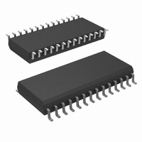
COP8SGR728M7/NOPB National Semiconductor, COP8SGR728M7/NOPB Datasheet - Page 37

COP8SGR728M7/NOPB
Manufacturer Part Number
COP8SGR728M7/NOPB
Description
MCU 8BIT CMOS ROM OTP 28-SOIC
Manufacturer
National Semiconductor
Series
COP8™ 8SGr
Datasheet
1.COP8SGE728N8NOPB.pdf
(62 pages)
Specifications of COP8SGR728M7/NOPB
Core Processor
COP8
Core Size
8-Bit
Speed
15MHz
Connectivity
Microwire/Plus (SPI), UART/USART
Peripherals
POR, PWM, WDT
Number Of I /o
24
Program Memory Size
32KB (32K x 8)
Program Memory Type
OTP
Ram Size
512 x 8
Voltage - Supply (vcc/vdd)
2.7 V ~ 5.5 V
Oscillator Type
Internal
Operating Temperature
-40°C ~ 125°C
Package / Case
28-SOIC
Data Bus Width
8 bit
Maximum Clock Frequency
15 MHz
Data Ram Size
512 B
Number Of Programmable I/os
40
Number Of Timers
3
Height
2.34 mm
Interface Type
USART
Length
17.91 mm
Maximum Operating Temperature
+ 125 C
Minimum Operating Temperature
- 40 C
Supply Voltage (max)
5.5 V
Supply Voltage (min)
2.7 V
Width
7.49 mm
For Use With
COP8SG-EPU - BOARD PROTOTYPE/TARGET COP8
Lead Free Status / RoHS Status
Lead free / RoHS Compliant
Eeprom Size
-
Data Converters
-
Lead Free Status / Rohs Status
Details
Other names
COP8SGR728M7
10.0 Interrupts
10.3.1 VIS Execution
When the VIS instruction is executed it activates the arbitra-
tion logic. The arbitration logic generates an even number
between E0 and FE (E0, E2, E4, E6 etc...) depending on
which active interrupt has the highest arbitration ranking at
the time of the 1st cycle of VIS is executed. For example, if
the software trap interrupt is active, FE is generated. If the
external interrupt is active and the software trap interrupt is
not, then FA is generated and so forth. If the only active
interrupt is software trap, than E0 is generated. This number
replaces the lower byte of the PC. The upper byte of the PC
(Continued)
FIGURE 26. VIS Operation
37
remains unchanged. The new PC is therefore pointing to the
vector of the active interrupt with the highest arbitration
ranking. This vector is read from program memory and
placed into the PC which is now pointed to the 1st instruction
of the service routine of the active interrupt with the highest
arbitration ranking.
Figure 26 illustrates the different steps performed by the VIS
instruction. Figure 27 shows a flowchart for the VIS instruc-
tion.
The non-maskable interrupt pending flag is cleared by the
RPND (Reset Non-Maskable Pending Bit) instruction (under
certain conditions) and upon RESET.
10131729
www.national.com


