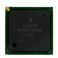
MCF5471ZP200 Freescale Semiconductor, MCF5471ZP200 Datasheet - Page 12

MCF5471ZP200
Manufacturer Part Number
MCF5471ZP200
Description
IC MPU 32BIT COLDF 388-PBGA
Manufacturer
Freescale Semiconductor
Series
MCF547xr
Datasheet
1.MCF5472VR200.pdf
(34 pages)
Specifications of MCF5471ZP200
Core Processor
Coldfire V4E
Core Size
32-Bit
Speed
200MHz
Connectivity
EBI/EMI, Ethernet, I²C, SPI, UART/USART, USB
Peripherals
DMA, PWM, WDT
Number Of I /o
99
Program Memory Type
ROMless
Ram Size
32K x 8
Voltage - Supply (vcc/vdd)
1.43 V ~ 1.58 V
Oscillator Type
External
Operating Temperature
0°C ~ 70°C
Package / Case
388-BGA
Family Name
MCF5xxx
Device Core
ColdFire V4e
Device Core Size
32b
Frequency (max)
200MHz
Instruction Set Architecture
RISC
Supply Voltage 1 (typ)
1.5/3.3V
Operating Supply Voltage (max)
1.58/3.6V
Operating Supply Voltage (min)
1.43/3V
Operating Temp Range
0C to 70C
Operating Temperature Classification
Commercial
Mounting
Surface Mount
Pin Count
388
Package Type
BGA
For Use With
M5475EVBGHS - KIT DEV GHS FOR M5475EVBM5474GFE - MODULE M5474 FIRE ENGINEM5474LITEKIT - KIT DEV FOR MCF547X
Lead Free Status / RoHS Status
Contains lead / RoHS non-compliant
Eeprom Size
-
Program Memory Size
-
Data Converters
-
Lead Free Status / Rohs Status
Not Compliant
Available stocks
Company
Part Number
Manufacturer
Quantity
Price
Company:
Part Number:
MCF5471ZP200
Manufacturer:
Freescale
Quantity:
92
Company:
Part Number:
MCF5471ZP200
Manufacturer:
MOTOLOLA
Quantity:
490
Reset Timing Specifications
7
Table 9
Figure 10
8
A multi-function external bus interface called FlexBus is provided on the MCF54
slave-only devices up to a maximum bus frequency of 66 MHz. It can be directly connected to asynchronous or synchronous
devices such as external boot ROMs, flash memories, gate-array logic, or other simple target (slave) devices with little or no
additional circuitry. For asynchronous devices, a simple chip-select based interface can be used. The FlexBus interface has six
general purpose chip-selects (FBCS[5:0]). Chip-select FBCS0 can be dedicated to boot ROM access and can be programmed
to be byte (8 bits), word (16 bits), or longword (32 bits) wide. Control signal timing is compatible with common ROM / flash
memories.
12
lists specifications for the reset timing parameters shown in
shows reset timing for the values in
Reset Timing Specifications
FlexBus
Mode Select
1
Num
RSTI and FlexBus data lines are synchronized internally. Setup and hold
times must be met only if recognition on a particular clock is required.
R1
R2
R3
FlexBus
CLKIN
1
RSTI
NOTE:
MCF547x ColdFire
Valid to CLKIN (setup)
CLKIN to invalid (hold)
Mode selects are registered on the rising clock edge before
the cycle in which RSTI is recognized as being negated.
Table 9. Reset Timing Specifications
RSTI to invalid (hold)
RSTI pulse duration
R1
Characteristic
Table
Figure 10. Reset Timing
9.
®
Microprocessor, Rev. 4
R2
Figure 10
66 MHz CLKIN
Min
1.0
1.0
8
5
R1
R3
Max
7
—
—
—
—
2 with basic functionality to interface to
CLKIN cycles
Units
ns
ns
ns
Freescale Semiconductor


