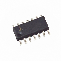
X40420S14I-B Intersil, X40420S14I-B Datasheet - Page 5

X40420S14I-B
Manufacturer Part Number
X40420S14I-B
Description
IC VOLT MON DUAL SUP/SW 14-SOIC
Manufacturer
Intersil
Type
Multi-Voltage Supervisorr
Datasheet
1.X40420S14Z-B.pdf
(25 pages)
Specifications of X40420S14I-B
Number Of Voltages Monitored
2
Output
Open Drain, Open Drain
Reset
Active High/Active Low
Reset Timeout
Adjustable/Selectable
Voltage - Threshold
2.6V, 4.6V
Operating Temperature
-40°C ~ 85°C
Mounting Type
Surface Mount
Package / Case
14-SOIC (3.9mm Width), 14-SOL
Lead Free Status / RoHS Status
Contains lead / RoHS non-compliant
Available stocks
Company
Part Number
Manufacturer
Quantity
Price
Company:
Part Number:
X40420S14I-B
Manufacturer:
Intersil
Quantity:
100
PRINCIPLES OF OPERATION
Power-on Reset
Applying power to the X40420, X40421 activates a
Power-on Reset Circuit that pulls the RESET/RESET
pins active. This signal provides several benefits.
– It prevents the system microprocessor from starting
– It prevents the processor from operating prior to sta-
– It allows time for an FPGA to download its configura-
– It prevents communication to the EEPROM, greatly
When V
for t
(X40421) and RESET (X40420) pin allowing the system
to begin operation.
Figure 1. Connecting a Manual Reset Push-Button
Manual Reset
By connecting a push-button directly from MR to
ground, the designer adds manual system reset capa-
bility. The MR pin is LOW while the push-button is
closed and RESET/RESET pin remains LOW for
t
thereafter. A weak pull up resistor is connected to the
MR pin.
Low Voltage V1 Monitoring
During operation, the X40420, X40421 monitors the
V
below a preset minimum V
prevents the microprocessor from operating in a
power fail or brownout condition. The V1FAIL signal
remains active until the voltage drops below 1V. It also
remains active until V
for
PURST
CC
to operate with insufficient voltage.
bilization of the oscillator.
tion prior to initialization of the circuit.
reducing the likelihood of data corruption on power-up.
t
PURST
PURST
level and asserts RESET if supply voltage falls
System
Reset
or till the push-button is released and for t
CC
.
(selectable) the circuit releases the RESET
exceeds the device V
X40420, X40421
RESET
CC
MR
returns and exceeds V
5
TRIP1
TRIP1
. The RESET signal
threshold value
Manual
Reset
X40420, X40421
PURST
TRIP1
Low Voltage V2 Monitoring
The X40420, X40421 also monitors a second voltage
level and asserts V2FAIL if the voltage falls below a pre-
set minimum V
with RESET to prevent the microprocessor from operat-
ing in a power fail or brownout condition or used to inter-
rupt the microprocessor with notification of an impending
power failure. The V2FAIL signal remains active until the
V
until V2MON returns and exceeds V
V2MON voltage monitor is powered by V
and V
Figure 2. Two Uses of Multiple Voltage Monitoring
WATCHDOG TIMER
The Watchdog Timer circuit monitors the microproces-
sor activity by monitoring the SDA and SCL pins. A
standard read or write sequence to any slave address
byte restarts the watchdog timer and prevents the
WDO signal to go active. A minimum sequence to
reset the watchdog timer requires four microprocessor
instructions namely, a Start, Clock Low, Clock High
and Stop. The state of two nonvolatile control bits in
the Status Register determine the watchdog timer
period. The microprocessor can change these watch-
dog bits by writing to the X40420, X40421 control reg-
ister.
Notice: No external components required to monitor two voltages.
CC
Unreg.
Supply
Resistors selected so 3V appears on V2MON when unregulated
drops below 1V (V
BATT
Unreg.
Supply
go away, V2MON cannot be monitored.
R
R
Reg
Reg
3V
5V
TRIP2
. The V2FAIL signal is either ORed
Reg
supply reaches 6V.
5V
V
V2MON
CC
CC
X40421
falling). It also remains active
V2MON
V
RESET
V2FAIL
CC
X40420
RESET
V2FAIL
TRIP2
V
OUT
.
V
OUT
OUT.
May 25, 2006
System
Reset
If V
System
Reset
CC


