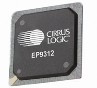
EP9312-CB Cirrus Logic Inc, EP9312-CB Datasheet - Page 284

EP9312-CB
Manufacturer Part Number
EP9312-CB
Description
System-on-Chip Processor
Manufacturer
Cirrus Logic Inc
Series
EP9r
Datasheets
1.EP9307-CRZ.pdf
(824 pages)
2.EP9312-IBZ.pdf
(4 pages)
3.EP9312-CB.pdf
(62 pages)
4.EP9312-CB.pdf
(17 pages)
Specifications of EP9312-CB
Peak Reflow Compatible (260 C)
No
A/d Converter
12 Bits
Leaded Process Compatible
No
No. Of I/o Pins
65
Package / Case
352-BGA
Core Processor
ARM9
Core Size
16/32-Bit
Speed
200MHz
Connectivity
EBI/EMI, EIDE, Ethernet, I²C, IrDA, Keypad/Touchscreen, SPI, UART/USART, USB
Peripherals
AC'97, DMA, I²:S, LCD, LED, MaverickKey, POR, PWM, WDT
Number Of I /o
16
Program Memory Type
ROMless
Ram Size
32K x 8
Voltage - Supply (vcc/vdd)
1.65 V ~ 3.6 V
Data Converters
A/D 8x12b
Oscillator Type
External
Operating Temperature
0°C ~ 70°C
Processor Series
EP93xx
Core
ARM920T
Data Bus Width
32 bit
3rd Party Development Tools
MDK-ARM, RL-ARM, ULINK2
Lead Free Status / RoHS Status
Contains lead / RoHS non-compliant
Eeprom Size
-
Program Memory Size
-
Lead Free Status / Rohs Status
No
Other names
598-1257
Available stocks
Company
Part Number
Manufacturer
Quantity
Price
Part Number:
EP9312-CB
Manufacturer:
CIRRUS
Quantity:
20 000
- EP9307-CRZ PDF datasheet
- EP9312-IBZ PDF datasheet #2
- EP9312-CB PDF datasheet #3
- EP9312-CB PDF datasheet #4
- Current page: 284 of 824
- Download datasheet (13Mb)
8
8-20
Graphics Accelerator
EP93xx User’s Guide
Note: Setting the source direction bits different from the destination direction bits is illegal and
E. Write the desired value to the HEIGHT field in the
F. The
G. The INTEN bit must configured to enable or disable an interrupt signal to the ARM
H. After Step G is complete, write EN = ‘1’ to start the Block Copy function.
I. Wait for an interrupt or poll for EN = ‘0’. When the EN bit is cleared to ‘0’, the Block
will have unpredictable results.
10 - 1 = 9 = 0x9.
same size for the source and the destination. Setting the PACKD bit allows transfers
from images that are packed into whole word areas.
appropriate function.
for the appropriate function.
from the source to be compared with the transparency pixel pattern to determine if
the destination pixel is to be modified before it is written. Without this bit enabled, a
direct block copy would occur.
bits control the direction for the line accumulator, Y, and the word/pixel counter, X. In
a left to right and top to bottom transfer:
For example, a 20-pixels x 10-lines image has a height of 10 lines. So, HEIGHT =
The PACKD bit must be configured to indicate if the image to be copied has the
The P bits must be configured for the BPP depth of the image to be copied.
When using the AND/OR/XOR mask function, the M bits must be configured for the
When using the AND/OR/XOR destination function, the D bits must be configured
When using transparency, the TRANS bit must be enabled to ‘1’. This allows data
The SYDIR, SXDIR and DYDIR, DXDIR direction bits must be configured. These
refer to the note in
where HEIGHT = the height in lines of the image that is to be copied minus 1.
previous graphics instruction. The EOI bit field must be cleared to ‘0’ regardless of
the interrupt enable status.
Core that occurs upon completion of the acceleration function.
Copy function sequence is done.
(1).if the destination is not exactly the same as the source, or
(2).if the destination partially overlaps the source and has a destination starting
“BLOCKCTRL”
word address greater than the source starting word address, then the source
information may be corrupted before being read. For this condition, the
direction bits for the transfer must be changed from left to right and top to
bottom to right to left and bottom to top.
Section 8.5.2.4 on page
register must be cleared to 0x0. This action clears out the
Copyright 2007 Cirrus Logic
8-12.
“BLKDESTHEIGHT”
register,
DS785UM1
Related parts for EP9312-CB
Image
Part Number
Description
Manufacturer
Datasheet
Request
R

Part Number:
Description:
IC ARM920T MCU 200MHZ 352-PBGA
Manufacturer:
Cirrus Logic Inc
Datasheet:

Part Number:
Description:
IC ARM9 SOC UNIVERSAL 352PBGA
Manufacturer:
Cirrus Logic Inc
Datasheet:

Part Number:
Description:
IC ARM920T MCU 200MHZ 352-PBGA
Manufacturer:
Cirrus Logic Inc
Datasheet:

Part Number:
Description:
IC Universal Platform ARM9 SOC Prcessor
Manufacturer:
Cirrus Logic Inc
Datasheet:

Part Number:
Description:
IC Universal Platform ARM9 SOC Prcessor
Manufacturer:
Cirrus Logic Inc
Datasheet:

Part Number:
Description:
Development Kit
Manufacturer:
Cirrus Logic Inc
Datasheet:

Part Number:
Description:
Development Kit
Manufacturer:
Cirrus Logic Inc
Datasheet:

Part Number:
Description:
High-efficiency PFC + Fluorescent Lamp Driver Reference Design
Manufacturer:
Cirrus Logic Inc
Datasheet:

Part Number:
Description:
Development Kit
Manufacturer:
Cirrus Logic Inc
Datasheet:

Part Number:
Description:
Development Kit
Manufacturer:
Cirrus Logic Inc
Datasheet:

Part Number:
Description:
Development Kit
Manufacturer:
Cirrus Logic Inc
Datasheet:

Part Number:
Description:
Development Kit
Manufacturer:
Cirrus Logic Inc
Datasheet:

Part Number:
Description:
Ref Bd For Speakerbar MSA & DSP Products
Manufacturer:
Cirrus Logic Inc


