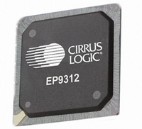
EP9312-CB Cirrus Logic Inc, EP9312-CB Datasheet - Page 767

EP9312-CB
Manufacturer Part Number
EP9312-CB
Description
System-on-Chip Processor
Manufacturer
Cirrus Logic Inc
Series
EP9r
Datasheets
1.EP9307-CRZ.pdf
(824 pages)
2.EP9312-IBZ.pdf
(4 pages)
3.EP9312-CB.pdf
(62 pages)
4.EP9312-CB.pdf
(17 pages)
Specifications of EP9312-CB
Peak Reflow Compatible (260 C)
No
A/d Converter
12 Bits
Leaded Process Compatible
No
No. Of I/o Pins
65
Package / Case
352-BGA
Core Processor
ARM9
Core Size
16/32-Bit
Speed
200MHz
Connectivity
EBI/EMI, EIDE, Ethernet, I²C, IrDA, Keypad/Touchscreen, SPI, UART/USART, USB
Peripherals
AC'97, DMA, I²:S, LCD, LED, MaverickKey, POR, PWM, WDT
Number Of I /o
16
Program Memory Type
ROMless
Ram Size
32K x 8
Voltage - Supply (vcc/vdd)
1.65 V ~ 3.6 V
Data Converters
A/D 8x12b
Oscillator Type
External
Operating Temperature
0°C ~ 70°C
Processor Series
EP93xx
Core
ARM920T
Data Bus Width
32 bit
3rd Party Development Tools
MDK-ARM, RL-ARM, ULINK2
Lead Free Status / RoHS Status
Contains lead / RoHS non-compliant
Eeprom Size
-
Program Memory Size
-
Lead Free Status / Rohs Status
No
Other names
598-1257
Available stocks
Company
Part Number
Manufacturer
Quantity
Price
Part Number:
EP9312-CB
Manufacturer:
CIRRUS
Quantity:
20 000
- EP9307-CRZ PDF datasheet
- EP9312-IBZ PDF datasheet #2
- EP9312-CB PDF datasheet #3
- EP9312-CB PDF datasheet #4
- Current page: 767 of 824
- Download datasheet (13Mb)
DS785UM1
26.2.2 Scan and Debounce
26.2.3 Interrupt Generation
Products are scanned based on the KEY_SCAN register value. Each complete array scan
starts with ROW7 and then progresses to ROW0, 1, and so on because of the pipelined
nature of the key scan controller. Keys in this ROW have precedence and are considered first
in the scan order because ROW7 is scanned first. When a key is pressed, it may
mechanically bounce for a up to 20 msec. The key array scan circuit will count the number of
consecutive scans that decode to the same 1 or 2 first keys encountered from the start of a
scan.
When a preset scan count limit is reached (counted by the DEBOUNCE_COUNT counter),
the key is considered to be de-bounced and an interrupt will occur. If a scan does not decode
the same 1 or 2 first keys as the previous scan, then the scan count will be reset. The scan
count limit is adjustable from 0 to 255 scans by writing to the DEBOUNCE_COUNT register
in the chip. The register is written with the complement of the desired scan count limit.
Typically a scan count limit of 3 is used.
Key arrays may have significant capacitance. If a key is pressed at a location ROWY, COLX,
the capacitance associated with COLX is discharged when the ROWY line is driven low
during the scan. When ROWY + 1 is driven, the capacitance associated with COLX must
then charge to a logic 1 passively before the COL inputs are sampled. If not, an erroneous
key press will be detected. For fast scan times, the time to charge the key array between
column samples is reduced. To reduce the time to charge the key array, the back drive
feature may be used. When back drive is enabled, the column lines and row lines are all
driven high for a short period of time between ROW scanning time to charge the array
capacitance.
An interrupt is generated whenever the key scanner detects a new stable set of keys. This
means that an interrupt occurs after a key is pressed and then after the key is released. An
interrupt will also occur if the first or second pressed keys in the array change to different
keys. When the interrupt occurs, the number of decoded keys pressed and the array
coordinates of the pressed keys are stored. The interrupt signal is maintained by a flip flop.
The interrupt flip flop is cleared when the key register is read by the ARM Core. The interrupt
condition can also be read by the ARM Core. Interrupt conditions are 1 key, 2 keys, and no
keys.
Assume that the keys may bounce for up to 20 msec and each scan is roughly 8 msec and
the scan count limit is set to 3 then an interrupt will occur between 24 and 44 msec after a key
is pressed or released. If a scan count limit of 0 is set by writing 0xFF to the de-bounce count
pre-load register then an interrupt will only occur the first time a key is pressed. No further
interrupts will occur because the DEBOUNCE_COUNT counter will always be reset to its
terminal count.
If an interrupt is ignored, then a subsequent interrupt will be pending until the first interrupt is
serviced. If further keypad activity occurs after an interrupt is pending then the most recent
de-bounced and decoded event will become pending and the previous pending conditions
will be lost.
Copyright 2007 Cirrus Logic
EP93xx User’s Guide
Keypad Interface
26-5
26
Related parts for EP9312-CB
Image
Part Number
Description
Manufacturer
Datasheet
Request
R

Part Number:
Description:
IC ARM920T MCU 200MHZ 352-PBGA
Manufacturer:
Cirrus Logic Inc
Datasheet:

Part Number:
Description:
IC ARM9 SOC UNIVERSAL 352PBGA
Manufacturer:
Cirrus Logic Inc
Datasheet:

Part Number:
Description:
IC ARM920T MCU 200MHZ 352-PBGA
Manufacturer:
Cirrus Logic Inc
Datasheet:

Part Number:
Description:
IC Universal Platform ARM9 SOC Prcessor
Manufacturer:
Cirrus Logic Inc
Datasheet:

Part Number:
Description:
IC Universal Platform ARM9 SOC Prcessor
Manufacturer:
Cirrus Logic Inc
Datasheet:

Part Number:
Description:
Development Kit
Manufacturer:
Cirrus Logic Inc
Datasheet:

Part Number:
Description:
Development Kit
Manufacturer:
Cirrus Logic Inc
Datasheet:

Part Number:
Description:
High-efficiency PFC + Fluorescent Lamp Driver Reference Design
Manufacturer:
Cirrus Logic Inc
Datasheet:

Part Number:
Description:
Development Kit
Manufacturer:
Cirrus Logic Inc
Datasheet:

Part Number:
Description:
Development Kit
Manufacturer:
Cirrus Logic Inc
Datasheet:

Part Number:
Description:
Development Kit
Manufacturer:
Cirrus Logic Inc
Datasheet:

Part Number:
Description:
Development Kit
Manufacturer:
Cirrus Logic Inc
Datasheet:

Part Number:
Description:
Ref Bd For Speakerbar MSA & DSP Products
Manufacturer:
Cirrus Logic Inc


