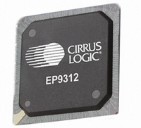
EP9312-CB Cirrus Logic Inc, EP9312-CB Datasheet - Page 405

EP9312-CB
Manufacturer Part Number
EP9312-CB
Description
System-on-Chip Processor
Manufacturer
Cirrus Logic Inc
Series
EP9r
Datasheets
1.EP9307-CRZ.pdf
(824 pages)
2.EP9312-IBZ.pdf
(4 pages)
3.EP9312-CB.pdf
(62 pages)
4.EP9312-CB.pdf
(17 pages)
Specifications of EP9312-CB
Peak Reflow Compatible (260 C)
No
A/d Converter
12 Bits
Leaded Process Compatible
No
No. Of I/o Pins
65
Package / Case
352-BGA
Core Processor
ARM9
Core Size
16/32-Bit
Speed
200MHz
Connectivity
EBI/EMI, EIDE, Ethernet, I²C, IrDA, Keypad/Touchscreen, SPI, UART/USART, USB
Peripherals
AC'97, DMA, I²:S, LCD, LED, MaverickKey, POR, PWM, WDT
Number Of I /o
16
Program Memory Type
ROMless
Ram Size
32K x 8
Voltage - Supply (vcc/vdd)
1.65 V ~ 3.6 V
Data Converters
A/D 8x12b
Oscillator Type
External
Operating Temperature
0°C ~ 70°C
Processor Series
EP93xx
Core
ARM920T
Data Bus Width
32 bit
3rd Party Development Tools
MDK-ARM, RL-ARM, ULINK2
Lead Free Status / RoHS Status
Contains lead / RoHS non-compliant
Eeprom Size
-
Program Memory Size
-
Lead Free Status / Rohs Status
No
Other names
598-1257
Available stocks
Company
Part Number
Manufacturer
Quantity
Price
Part Number:
EP9312-CB
Manufacturer:
CIRRUS
Quantity:
20 000
- EP9307-CRZ PDF datasheet
- EP9312-IBZ PDF datasheet #2
- EP9312-CB PDF datasheet #3
- EP9312-CB PDF datasheet #4
- Current page: 405 of 824
- Download datasheet (13Mb)
DS785UM1
10.1.10.1.3 DMA_MEM_RD
10.1.10.1.4 DMA_MEM_WR
No data transfers occur in this state.
The DMA M2M Control FSM enters the DMA_MEM_RD state when a M2M channel has
received a software trigger to begin a transfer, that is, the START bit is set (CONTROL[4])
and CONTROL.TM = “00”; or when IDE or SSP asserts its request line and CONTROL.TM =
“01” or “10”; or when an external device asserts its DREQ o/p to the DMA and CONTROL.TM
= “01” or “10”. At least one of the BCRx registers must contain a valid value, otherwise the
DMA stays in the DMA_STALL state. For software triggered mode a valid BCR value is any
non-zero value. For external DMA mode a valid BCR value depends on the peripheral width
(programmed via the PW bits of the CONTROL register). For word/half-word/byte-wide
peripherals the BCR value must be greater than or equal to four/two/one respectively.
The DMA M2M Control FSM enters the DMA_MEM_RD state when a memory write transfer
has finished and the BCR register is still not equal to zero, that is, more data needs to be
transferred from memory-to-memory. For external bus and IDE/SSP transfers, BCR not-
equal-to 0 must be qualified with a DREQ before the DMA_MEM_RD state is entered again.
The DMA M2M Control FSM enters the DMA_MEM_RD state on exit from the
DMA_BWC_WAIT state, if all the data present in the data bay had been transferred to
memory when DMA_BWC_WAIT state was entered.
The DMA M2M Control FSM stays in this state until the data transfer from memory has
completed for software trigger mode, that is, the data bay is filled with 16 bytes (or less
depending on transfer size and BCR value etc.).
The DMA M2M Control FSM enters the DMA_MEM_RD state when the BCR register is equal
to zero for the current buffer, and the other buffer descriptors BCR register has been
programmed non-zero. DMA will proceed to do a memory read using the new buffer and the
NFB interrupt is generated, if enabled.
Data transfers from memory or external bus/device (depending on the CONTROL.TM bits),
occur in this state.
The DMA M2M Control FSM enters the DMA_MEM_WR state when a memory read transfer
has completed.
The DMA M2M Control FSM enters the DMA_MEM_WR state on exit from the
DMA_BWC_WAIT state, if all the data present in the data bay had not been transferred to
memory when DMA_BWC_WAIT state was entered.
The DMA M2M Control FSM stays in this state until the data transfer to memory has
completed, that is, the data bay is emptied.
Data transfers, to memory or external peripheral (depending on the CONTROL.TM bits),
occur in this state.
Copyright 2007 Cirrus Logic
EP93xx User’s Guide
DMA Controller
10-11
10
Related parts for EP9312-CB
Image
Part Number
Description
Manufacturer
Datasheet
Request
R

Part Number:
Description:
IC ARM920T MCU 200MHZ 352-PBGA
Manufacturer:
Cirrus Logic Inc
Datasheet:

Part Number:
Description:
IC ARM9 SOC UNIVERSAL 352PBGA
Manufacturer:
Cirrus Logic Inc
Datasheet:

Part Number:
Description:
IC ARM920T MCU 200MHZ 352-PBGA
Manufacturer:
Cirrus Logic Inc
Datasheet:

Part Number:
Description:
IC Universal Platform ARM9 SOC Prcessor
Manufacturer:
Cirrus Logic Inc
Datasheet:

Part Number:
Description:
IC Universal Platform ARM9 SOC Prcessor
Manufacturer:
Cirrus Logic Inc
Datasheet:

Part Number:
Description:
Development Kit
Manufacturer:
Cirrus Logic Inc
Datasheet:

Part Number:
Description:
Development Kit
Manufacturer:
Cirrus Logic Inc
Datasheet:

Part Number:
Description:
High-efficiency PFC + Fluorescent Lamp Driver Reference Design
Manufacturer:
Cirrus Logic Inc
Datasheet:

Part Number:
Description:
Development Kit
Manufacturer:
Cirrus Logic Inc
Datasheet:

Part Number:
Description:
Development Kit
Manufacturer:
Cirrus Logic Inc
Datasheet:

Part Number:
Description:
Development Kit
Manufacturer:
Cirrus Logic Inc
Datasheet:

Part Number:
Description:
Development Kit
Manufacturer:
Cirrus Logic Inc
Datasheet:

Part Number:
Description:
Ref Bd For Speakerbar MSA & DSP Products
Manufacturer:
Cirrus Logic Inc


