IPR-POSPHY4 Altera, IPR-POSPHY4 Datasheet
IPR-POSPHY4
Specifications of IPR-POSPHY4


Related parts for IPR-POSPHY4


IPR-POSPHY4 Summary of contents
Page 1
... POS-PHY Level 4 MegaCore Function User Guide 101 Innovation Drive San Jose, CA 95134 www.altera.com UG-IPPOSPHY4-10.1 POS-PHY Level 4 MegaCore Function Document last updated for Altera Complete Design Suite version: User Guide 10.1 December 2010 Document publication date: Subscribe ...
Page 2
... Altera warrants performance of its semiconductor products to current specifications in accordance with Altera's standard warranty, but reserves the right to make changes to any products and services at any time without notice. Altera assumes no responsibility or liability arising out of the application or use of any information, product, or service described herein except as expressly agreed to in writing by Altera. Altera customers are advised to obtain the latest version of device specifications before relying on any published information and before placing orders for products or services ...
Page 3
... Receiver Options . . . . . . . . . . . . . . . . . . . . . . . . . . . . . . . . . . . . . . . . . . . . . . . . . . . . . . . . . . . . . . . . . . . . . 3–16 Chapter 4. Functional Description—Receiver Features . . . . . . . . . . . . . . . . . . . . . . . . . . . . . . . . . . . . . . . . . . . . . . . . . . . . . . . . . . . . . . . . . . . . . . . . . . . . . . . . 4–1 Block Description . . . . . . . . . . . . . . . . . . . . . . . . . . . . . . . . . . . . . . . . . . . . . . . . . . . . . . . . . . . . . . . . . . . . . . . 4–2 Data Receiver and Serial-to-Parallel Converter (rx_data_phy_altlvds 4–2 DPA Channel Aligner (rx_data_phy_dpa 4–3 ALTLVDS_RX Megafunction . . . . . . . . . . . . . . . . . . . . . . . . . . . . . . . . . . . . . . . . . . . . . . . . . . . . . . . . . 4–4 Channel Aligner . . . . . . . . . . . . . . . . . . . . . . . . . . . . . . . . . . . . . . . . . . . . . . . . . . . . . . . . . . . . . . . . . . . . 4–4 December 2010 Altera Corporation Contents POS-PHY Level 4 MegaCore Function User Guide ...
Page 4
... Error Flagging and Handling . . . . . . . . . . . . . . . . . . . . . . . . . . . . . . . . . . . . . . . . . . . . . . . . . . . . . . . . . . . . 5–11 SPI-4.2 Error Detection and Handling . . . . . . . . . . . . . . . . . . . . . . . . . . . . . . . . . . . . . . . . . . . . . . . . . . . 5–11 Atlantic Interface Error Detection and Handling . . . . . . . . . . . . . . . . . . . . . . . . . . . . . . . . . . . . . . . . . 5–14 Missing SOP . . . . . . . . . . . . . . . . . . . . . . . . . . . . . . . . . . . . . . . . . . . . . . . . . . . . . . . . . . . . . . . . . . . . . . 5–15 Missing EOP . . . . . . . . . . . . . . . . . . . . . . . . . . . . . . . . . . . . . . . . . . . . . . . . . . . . . . . . . . . . . . . . . . . . . . 5–16 Signals . . . . . . . . . . . . . . . . . . . . . . . . . . . . . . . . . . . . . . . . . . . . . . . . . . . . . . . . . . . . . . . . . . . . . . . . . . . . . . . . 5–16 Avalon-MM Interface Register Map . . . . . . . . . . . . . . . . . . . . . . . . . . . . . . . . . . . . . . . . . . . . . . . . . . . . . . . 5–24 Latency Information . . . . . . . . . . . . . . . . . . . . . . . . . . . . . . . . . . . . . . . . . . . . . . . . . . . . . . . . . . . . . . . . . . . . 5–26 POS-PHY Level 4 MegaCore Function User Guide Contents December 2010 Altera Corporation ...
Page 5
... AC Timing Analysis . . . . . . . . . . . . . . . . . . . . . . . . . . . . . . . . . . . . . . . . . . . . . . . . . . . . . . . . . . . . . . . . . . . . F–4 Appendix G. Conversion from v2.2.x Introduction . . . . . . . . . . . . . . . . . . . . . . . . . . . . . . . . . . . . . . . . . . . . . . . . . . . . . . . . . . . . . . . . . . . . . . . . . . . G–1 Receiver Signals . . . . . . . . . . . . . . . . . . . . . . . . . . . . . . . . . . . . . . . . . . . . . . . . . . . . . . . . . . . . . . . . . . . . . . . . G–1 Transmitter Signals . . . . . . . . . . . . . . . . . . . . . . . . . . . . . . . . . . . . . . . . . . . . . . . . . . . . . . . . . . . . . . . . . . . . . G–4 Additional Information Document Revision History . . . . . . . . . . . . . . . . . . . . . . . . . . . . . . . . . . . . . . . . . . . . . . . . . . . . . . . . . . . Info–1 How to Contact Altera . . . . . . . . . . . . . . . . . . . . . . . . . . . . . . . . . . . . . . . . . . . . . . . . . . . . . . . . . . . . . . . . Info–1 Typographic Conventions . . . . . . . . . . . . . . . . . . . . . . . . . . . . . . . . . . . . . . . . . . . . . . . . . . . . . . . . . . . . . Info–2 December 2010 Altera Corporation POS-PHY Level 4 MegaCore Function User Guide v ...
Page 6
... POS-PHY Level 4 MegaCore Function User Guide Contents December 2010 Altera Corporation ...
Page 7
... Altera does not verify compilation with MegaCore function versions older than one release. Device Family Support MegaCore functions can provide the types of support for target Altera device families described in Table 1–2. Altera IP Core Device Support Levels FPGA Device Families Preliminary— ...
Page 8
... Table 1–3 shows the level of support offered by the POS-PHY Level 4 MegaCore function to each Altera device family. Table 1–3. Device Family Support Device Family ® Arria GX Arria II GX Arria II GZ ® Cyclone Cyclone II Cyclone III Cyclone III LS Cyclone IV HardCopy II HardCopy III HardCopy IV E ® ...
Page 9
... Status framing hysteresis (good and bad thresholds) ■ DIP-4 hysteresis (good and bad thresholds) ■ ■ IP functional simulation models for use in Altera-supported VHDL and Verilog HDL simulators ■ I-Tested certification General Description The packet over SONET/SDH physical layer (POS-PHY) Level 4 interface, first developed by the SATURN Internetworking Forum (OIF) as the System Packet Interface Level 4— ...
Page 10
... Figure 1–1 shows a full-duplex POS-PHY Level 4 MegaCore function configured for the link layer in an Altera FPGA device. Figure 1–1. POS-PHY Level 4 MegaCore Function as Link Layer Configuration SPI-4.2 Interface OC-192 POS-PHY Level 4 POS Framer or POS-PHY Level 4 10 GbitE MAC Transmitter Figure 1–2 shows a full-duplex POS-PHY Level 4 MegaCore function configured for the PHY layer in an Altera FPGA device ...
Page 11
... For further information on this interface, refer to the Specification. Avalon-MM Interface The Altera Avalon-MM interface is a simple bus architecture that connects on-chip processors (or external processor interfaces) and peripherals. The Avalon-MM interface specifies the port connections between master and slave components, and specifies the timing by which these components communicate. ...
Page 12
... Chapter 1: About This MegaCore Function Performance and Resource Utilization Memory Blocks clk (1) f (MHz) M9K MAX 10 179 10 175 11 162 9 140 10 146 Memory Blocks clk (1) f (MHz) MAX M9K 10 193 17 266 23 138 10 172 17 275 23 158 11 203 14 260 8 151 December 2010 Altera Corporation ...
Page 13
... Transmitter 128 10 Table 1–7. Performance—Individual Buffers Mode—Cyclone III Device (Part Parameters Data Path Width Data Flow Direction (bits) 32 Receiver 32 32 December 2010 Altera Corporation Logic ALUTs Number of Registers Ports 4 875 850 4 944 1,326 4 1,177 1,456 10 901 939 10 1,042 ...
Page 14
... MAX 36 139 37 253 71 149 84 126 85 230 10 130 10 193 18 146 34 134 34 179 66 125 82 128 82 156 clk Memory f (MHz) MAX Blocks EP4SGX70 EP4SGX230 (M9K) DF29C3 DF29C3ES 21 182 159 40 270 268 78 165 149 45 140 144 88 255 254 December 2010 Altera Corporation ...
Page 15
... After you purchase a license for POS-PHY Level 4 MegaCore function, you can request a license file from the on your computer. When you request a license file, Altera emails you a license.dat file. If you do not have Internet access, contact your local Altera representative. December 2010 Altera Corporation ...
Page 16
... OpenCore Plus Evaluation With Altera’s free OpenCore Plus evaluation feature, you can perform the following actions: Simulate the behavior of a megafunction (Altera MegaCore function or AMPP ■ megafunction) within your system Verify the functionality of your design, as well as evaluate its size and speed ■ ...
Page 17
... Determine your design’s constraints and performance requirements and then parameterize the POS-PHY Level 4 MegaCore function in IP Toolbench. 1 Not all parameters are supported by, or are relevant for, every MegaCore function variation. December 2010 Altera Corporation 2. Getting Started ® II software. The sections in this chapter Specify Parameters ...
Page 18
... A generated HDL file for Quartus II synthesis. This file is automatically added to your Quartus II project. You should not modify this file. A timing and resource netlist for use in some third-party synthesis tools. Chapter 2: Getting Started Specify Parameters Chapter 3, Parameter Settings. Description December 2010 Altera Corporation ...
Page 19
... MegaCore function. Instantiate the entity defined by this file inside of your design. Include this file when compiling your design in the Quartus II software. Verilog HDL IP functional simulation model. and the Simulating Altera IP in Third-Party chapter in volume 3 of the Quartus II Handbook. 2–3 POS-PHY Level 4 MegaCore Function User Guide ...
Page 20
... Altera provides models you can use for functional verification of the POS-PHY Level 4 MegaCore function within your design. A Verilog HDL testbench, including scripts to run it, is also provided. This testbench, for use with the ModelSim-Altera simulator or other simulator tools via NativeLink, demonstrates how to instantiate a model in a design ...
Page 21
... When you have entered the required information for your new testbench, click OK in the New Test Bench Settings dialog box. 9. Click OK in the Test Benches dialog box and then click OK in the Settings dialog box. December 2010 Altera Corporation (refer also to Figure 2–2 on page Parameter < ...
Page 22
... Compile the Design and Program a Device You can use the Quartus II software to compile your design. Refer to Quartus II Help for instructions on compiling your design. After you have compiled your design, program your targeted Altera device and verify your design in hardware. POS-PHY Level 4 MegaCore Function User Guide ...
Page 23
... Basic Parameters Figure 3–1 shows the basic parameters tab. Figure 3–1. Basic Parameters Device Family Select the device family. PHY Level 4 MegaCore function supports. December 2010 Altera Corporation 3. Parameter Settings ® function by specifying parameters ® Plug-in Manager in the Table 1–3 on page 1–2 ...
Page 24
... POS-PHY Level 4 MegaCore Function User Guide Device Family ™ “DPA Channel Aligner 4–3. Chapter 3: Parameter Settings Basic Parameters LVDS Rate (Mbps) 840 1,000 622 622 622 622 1,040 840 1,040 1,040 1,250 1,250 1,250 1,000 interface transmitter where December 2010 Altera Corporation ...
Page 25
... Atlantic buffer in the same order received. The shared buffer with embedded addressing mode is smaller than the individual buffers mode, and allows you to develop your own buffering and status generation implementation. December 2010 Altera Corporation “Performance and Resource Utilization” on page POS-PHY Level 4 MegaCore Function User Guide 3– ...
Page 26
... The POS-PHY Level 4 MegaCore function supports the following sizes (per buffer): 512 bytes ■ ■ 1,024 bytes POS-PHY Level 4 MegaCore Function User Guide 5–3. 4–7. Chapter 3: Parameter Settings Basic Parameters “Individual “Individual December 2010 Altera Corporation ...
Page 27
... For the Status channel I/O standard, either LVTTL or LVDS, select LVDS to implement the optional lower bandwidth LVDS status operation (refer to the OIF- SPI4-02.1 specification). December 2010 Altera Corporation Table 3–2 shows the Atlantic data widths supported for each internal Supported Atlantic Data Width (Bits) ...
Page 28
... Atlantic error checking is often desirable for receivers, but less applicable for transmitters because the incoming user-Atlantic data may be presumed correct. POS-PHY Level 4 MegaCore Function User Guide shows the Optional Features tab. Chapter 3: Parameter Settings Optional Features December 2010 Altera Corporation ...
Page 29
... The Pessimistic mode causes the latency in receiving a valid status message to be calendar multiplier × calendar length tsclk cycles longer than the optimistic mode. This length is significant for systems with large calendar length or large calendar multiplier values. December 2010 Altera Corporation 3–7 POS-PHY Level 4 MegaCore Function User Guide ...
Page 30
... SPI4.2 Specification. When the signal goes low, the MegaCore function states it is out of synchronization and requests a new training sequence. POS-PHY Level 4 MegaCore Function User Guide Chapter 3: Parameter Settings “Individual Buffers Transmit Scheduler (tx_sched)” on December 2010 Altera Corporation Optional Features ...
Page 31
... Turn on Safe External (User Controlled) Status, to ensure the sent status avoids FIFO buffer overflow (refer to to ensure the sent status is always the user status (refer to buffer fill level. December 2010 Altera Corporation Table 3–3). Turn off Safe External (User Controlled) Status, POS-PHY Level 4 MegaCore Function User Guide 3– ...
Page 32
... When you select 2 FIFO RAM blocks, the timing performance of the MegaCore function may decrease (because the memory rdata bus is unregistered, as opposed to registered for 4 FIFO RAM blocks). Altera recommends that you do full compilations for both configurations before deciding which one to choose. 1 Use 2 FIFO RAM block only if it gives an improvement in memory utilization and if your timing requirements are still met ...
Page 33
... M4K 8,192 24 M4K Note to Table 3–5: (1) Stratix II device, receive (Rx), shared buffer, data path width 32, parity enabled. December 2010 Altera Corporation Figure 3–3 shows the comparison of FIFO RAM blocks. 4 FIFO RAM Blocks FIFO Block 0 (size = fifo_size/4) FIFO Block 1 (size = fifo_size/4) Write Side ...
Page 34
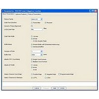
... A port with twice the calendar entries of all other ports nominally uses twice as much bandwidth on the SPI-4.2 interface depending on the data characteristics. Ports can be disabled by removing them from the calendar. POS-PHY Level 4 MegaCore Function User Guide shows the Protocol Parameters tab. Chapter 3: Parameter Settings Protocol Parameters December 2010 Altera Corporation ...
Page 35
... The transmitter receives the first calendar-select word of the new frame and detects the toggle. The transmitter toggles the used calendar multiplier, calendar length, and ■ calendar to interpret the next status frame. December 2010 Altera Corporation Appendix E). Table C–1 on page C–1 of the “ ...
Page 36
... MaxT parameter, and no more than the value of the MaxT parameter plus the burst unit size. POS-PHY Level 4 MegaCore Function User Guide Chapter 3: Parameter Settings for the relation of AE and AF. December 2010 Altera Corporation Protocol Parameters ...
Page 37
... The N-byte values depend on the Atlantic interface width and on the Lite transmitter setting. Table 3–6 Table 3–6. N-Byte Values Datapath Width 32 64 128 December 2010 Altera Corporation shows the N-byte values, based on the transmitter's settings. Atlantic Interface Lite Transmitter Width 128 ...
Page 38
... MaxBurst1 and MaxBurst2 values is application-specific, and requires an analysis of the data flows, beyond the scope of this user guide. POS-PHY Level 4 MegaCore Function User Guide AE Starving Hungry Lmax + ε Lmax + MaxBurst1+ ε 3–5: Chapter 3: Parameter Settings Protocol Parameters AF (Full) Satisfied Lmax + MaxBurst2+ ε December 2010 Altera Corporation ...
Page 39
... The receiver may need to receive more control word DIP-4 errors than the DIP-4 bad threshold parameter set in the wizard, for stat_rd_dip4_oos to go high. f For more information, refer to Service Indication” on page December 2010 Altera Corporation “DIP-4 Marking” on page 4–17 4–18. POS-PHY Level 4 MegaCore Function User Guide 3–17 and “ ...
Page 40
... POS-PHY Level 4 MegaCore Function User Guide Chapter 3: Parameter Settings Protocol Parameters December 2010 Altera Corporation ...
Page 41
... Performs start-of-packet (SOP) alignment and Atlantic conversion ■ Buffers packets on a per-port or per-interface basis ■ ■ Detects buffer fill levels and generates the status channel December 2010 Altera Corporation 4. Functional Description—Receiver ® function consists of the main SPI-4.2 processing ™ first-in first-out (FIFO) buffers. When the POS-PHY ...
Page 42
... DPA Channel Data Aligner Processor Status FSM Status Status Hold Register Status Calculator rav_clk ® III, Stratix II, Stratix GX, and Stratix devices Chapter 4: Functional Description—Receiver Block Description Atlantic Interface 0 Atlantic Buffer 0 Atlantic Interface N Atlantic Buffer N rxsys_clk December 2010 Altera Corporation ...
Page 43
... DPA block diagram. Figure 4–2. DPA and Channel Aligner Block Diagram rdclk Serial Data ALTLVDS_RX rdat/rctl Megafunction 16+1 (with DPA) December 2010 Altera Corporation SERDES Transmitter/Receiver ALTLVDS Megafunction User ALTDDIO Megafunction User Guide. lvds_reset 16+1 data_out data_out_algn Channel Aligner 128+/64+ ...
Page 44
... It then pulses the bits of the align[16:0] signal channel by channel until all channels are POS-PHY Level 4 MegaCore Function User Guide Chapter 4: Functional Description—Receiver Block Description December 2010 Altera Corporation ...
Page 45
... Whenever the MegaCore function aborts a packet by asserting the aN_arxerr signal (as in the odd size packet with LSB not cleared), the resulting packet is even sized, except in the DIP-4 optimistic mode. December 2010 Altera Corporation Alignment. “DIP-4 Marking” on page 4–17 4–18). POS-PHY Level 4 MegaCore Function User Guide 4– ...
Page 46
... SPI-4.2 bus. POS-PHY Level 4 MegaCore Function User Guide Chapter 4: Functional Description—Receiver 4–13. 4–10. December 2010 Altera Corporation Block Description “Error ...
Page 47
... The status PHY block (rx_stat_phy) generates rsclk given some reference clock: In 128-bit variations, the rsclk runs at the rdint_clk rate. ■ In 64-bit variations, the rsclk runs at 1/2 the rdint_clk rate. ■ In 32-bit variations, the rsclk runs at 1/4 of the rdint_clk rate. ■ December 2010 Altera Corporation 4–7 POS-PHY Level 4 MegaCore Function User Guide ...
Page 48
... This external control interface features an 8-bit address bus, a 2-bit status port value, and a valid signal (refer to POS-PHY Level 4 MegaCore Function User Guide Chapter 4: Functional Description—Receiver Appendix E and the 4–29). Figure 4–3). December 2010 Altera Corporation Block Description ® “Avalon- ...
Page 49
... Atlantic buffer overflows. The FIFO buffer status of each port is encoded in 2 bits (refer to transmitted synchronous to the rsclk. Table 4–1. Status Channel Field Descriptions (Part MSB LSB December 2010 Altera Corporation 2'b00 2'b00 2'b00 2'b01 2'bxx 2'bxx 8'd0 8'd0 8'd1 8'd1 8'd0 ...
Page 50
... FIFO buffers do not fill, otherwise backpressure is asserted via the SPI-4.2 status channel. POS-PHY Level 4 MegaCore Function User Guide Description STARVING—FIFO buffer is almost empty. MaxBurst1 credits should be granted in the far end scheduler. (1) rxsys_clk. Chapter 4: Functional Description—Receiver Clock Structure Appendix C, December 2010 Altera Corporation ...
Page 51
... PLL where it generates rdint_clk (×1). The PLL is required to provide 90° phase shift, so the ALTDDIO_IN megafunction samples in the centre of the data eye. A typical system may have a rdint_clk of 100 MHz, of which December 2010 Altera Corporation shows the multiple clock domain clocking structure for the rdint_clk ...
Page 52
... Processor 2 Worst Case Frequency Requirement 1.0 × rdint_clk 1.25 × rdint_clk 1.6 × rdint_clk rxsys_clk. Chapter 4: Functional Description—Receiver Reset Structure a0_arxclk Atlantic Atlantic Buffer 0 Interface 0 aN_arxclk (Note 2, 3) Atlantic Atlantic Interface N Buffer N rxsys_clk (Note 1) Chapter C, Optimum December 2010 Altera Corporation ...
Page 53
... The ctl_rd_dpa_force_unlock signal is not asserted until after start up. (2) The delay is to ensure the ctl_rd_dpa_force_unlock signal is asserted for at least one clock cycle. (3) The counter is intended to pulse the ctl_rd_dpa_force_unlock signal after the frame has been out of synchronization for some time. December 2010 Altera Corporation Example User Side Connections 17 ...
Page 54
... Training Control portion > 10 cycles). Assert err_rd_eightn for one clock cycle. Packet is marked as errored. Consider error as a missing EOP. Cleanly terminate packet internally as an EOP-Abort. (3) Process subsequent bursts as per missing SOP. December 2010 Altera Corporation ...
Page 55
... Single DIP-4 error current control word and preceding data. A DIP-4 error occurs when the DIP-4 calculated over the rdat line does not match the DIP-4 value in the control word. December 2010 Altera Corporation (Note 1), (2) Condition ■ ...
Page 56
... Marking” on 4–17. Assert err_ry_paddr. In the shared buffer with embedded addressing mode, the burst/packet is sent to the user logic, and the user logic to define and determine the course of action. In the individual buffers mode, the packet/burst is discarded. December 2010 Altera Corporation ...
Page 57
... SOP for that port is received. 1 Because of the logic required to track open packets per ports, this feature uses a large amount of logic for systems with many ports. December 2010 Altera Corporation 4–17 POS-PHY Level 4 MegaCore Function User Guide ...
Page 58
... If any DIP-4 errors are received in the current cycle, the counter is cleared control words are received, nothing happens. POS-PHY Level 4 MegaCore Function User Guide Chapter 4: Functional Description—Receiver Error Flagging and Handling December 2010 Altera Corporation ...
Page 59
... Atlantic Interface Error Detection and Handling When the Atlantic error checking parameter is turned on, a filtering block—the Atlantic FIFO buffer error checker—is instantiated at the write side of the FIFO buffer to ensure that the MegaCore function does not pass errored packets. December 2010 Altera Corporation (Note ...
Page 60
... If an EOP is forced, the aN_atxerr output signal ■ is asserted. Generally this signal can be ignored, unless the aN_atxeop signal is also asserted. Chapter 4: Functional Description—Receiver Error Flagging and Handling Response “Missing SOP” on page 4–22. December 2010 Altera Corporation ...
Page 61
... These error conditions do not correlate directly—in terms of latency—to the data going into, or coming out of, the FIFO buffer. 1 Altera recommends that you assert the ctl_ax_fifo_eopdav signal with the error checker to ensure the buffer is emptied in the event of an overflow. December 2010 Altera Corporation ...
Page 62
... Figure 4–10. Missing SOP Output Timing Diagram aN_arxsop aN_arx eop err_ry_msopN POS-PHY Level 4 MegaCore Function User Guide aN_arxtclk aN_arxena aN_arxerr Chapter 4: Functional Description—Receiver Error Flagging and Handling Figure 4–10). Missing SOP December 2010 Altera Corporation ...
Page 63
... Figure 4–13. Overflow aN_rxclk aN_arxena aN_arxsop aN_arxeop err_ry_fifo_oflwN aN_arxdav Good Packet December 2010 Altera Corporation 4–23 show that if a SOP is detected during an open packet, the Packet Interrupted Packet(s) 4–23 Packet B Good Packet POS-PHY Level 4 MegaCore Function User Guide ...
Page 64
... Locked signal directly from fast PLL in ALTVDS for full rate Asynchronous variations, or enhanced PLL in quarter-rate variations. Asynchronous reset signal directly to fast PLL in ALTVDS for Asynchronous full rate variations, or enhanced PLL in quarter-rate variations. Chapter 4: Functional Description—Receiver Signals Description Description “Reset Structure” on December 2010 Altera Corporation ...
Page 65
... Output err_aN_fifo_parityN Output stat_aN_fifo_emptyN December 2010 Altera Corporation (Note 1) Description Atlantic clock (one for each Atlantic interface). This input is absent and internally connected to rxsys_clk if a single clock domain is selected. Signals prefixed with aN_ are synchronous to this clock. Atlantic data available (one for each Atlantic interface). Asserted when the Atlantic FIFO buffer has at least ctl_ax_ftl bytes available to read ...
Page 66
... Status for port indicated by ctl_ry_extstat_adr. Input This value is ignored if ctl_ry_fifostatoverride is deasserted. Input - Controls the edge of rsclk on which transitions of Static rstat occur positive edge negative edge). rsclk constant Only change at reset. Chapter 4: Functional Description—Receiver Signals Description Description December 2010 Altera Corporation ...
Page 67
... December 2010 Altera Corporation Direction Clock Domain When asserted, the ctl_ry_rsfrm signal forces the receiver status channel into framing mode beginning at Input the end of the next frame. You can use ctl_ry_rsfrm to indicate that the receiver requires retraining. ...
Page 68
... This port is absent if DPA is turned off. When this signal is high, it indicates that the DPA PLL has locked. This port is absent if DPA is turned off. Forces the DPA circuitry and PLL to unlock and retrain. This port is absent if DPA is turned off. December 2010 Altera Corporation Signals ...
Page 69
... Avalon-MM Interface Register Map Table 4–12 lists the Avalon-MM interface registers. December 2010 Altera Corporation Clock Domain Main receiver data path sync output signal. Combination of DPA, channel aligner sync, and DIP-4 status. Indicates that the receiver has detected a training pattern. ...
Page 70
... If write, CALMEM_ADR is applied to the write address of RAM and CALMEM_DAT1 is applied to the write data. Read write indirect data If read, CALMEM_ADR is applied to read address of RAM, and resulting read data is captured in CALMEM_DAT1. Reserved Reserved. Chapter 4: Functional Description—Receiver Avalon-MM Interface Register Map Description December 2010 Altera Corporation ...
Page 71
... Figure 4–14 on page 4–31 receiver finish gives the receiver L mode. Figure 4–14 December 2010 Altera Corporation shows a picture of the L ) for a receiver using the individual buffers MAX Individual Buffers Mode Overview MAX Receiver MegaCore Function SPI-4 ...
Page 72
... Data Latency (Bytes on SPI-4.2 Interface) 272 288 152 160 36 72 Table 4–13 do not include the latency through the user-side buffers. Chapter 4: Functional Description—Receiver Latency Information Status Transmit Latency (Bytes on SPI-4.2 Interface) 320 320 320 320 320 320 December 2010 Altera Corporation ...
Page 73
... Notes to Figure 5–1: (1) The dotted lines illustrate the clock domain separations. (2) These blocks and signals are only present when the individual buffers mode is selected. December 2010 Altera Corporation 5. Functional Description—Transmitter ® function consists of the main SPI-4.2 processing ™ interface to the SPI-4.2 interface. ...
Page 74
... All address bits are passed through the buffer unaffected The shared buffer with embedded addressing mode supports two different backpressure mechanisms. POS-PHY Level 4 MegaCore Function User Guide Chapter 5: Functional Description—Transmitter Block Description December 2010 Altera Corporation ...
Page 75
... A starving status update loads the next-credit register with MaxBurst1. A hungry status update loads the next-credit register with MaxBurst2. A satisfied status update has no effect on the next-credits register. December 2010 Altera Corporation “Individual Buffers Transmit Scheduler (tx_sched)” on POS-PHY Level 4 MegaCore Function User Guide ...
Page 76
... Training Sequence Interval parameter (MaxT). If the status channel is receiving a continuous framing pattern on the status channel, the MegaCore function sends training patterns continuously. POS-PHY Level 4 MegaCore Function User Guide Chapter 5: Functional Description—Transmitter “Shared Buffer with 5–2. December 2010 Altera Corporation Block Description ...
Page 77
... For 128- and 64-bit variations, an ALTLVDS megafunction serializes the words into input high-speed tdat, tctl, and tdclk signals. The tdclk pin uses an output data pin, using the SERDES to send a repeating binary 10 pattern, guaranteeing minimal skew between the clock and data. December 2010 Altera Corporation 5–5 POS-PHY Level 4 MegaCore Function User Guide ...
Page 78
... Interface Register Map” on page Chapter 5: Functional Description—Transmitter Block Description 2'b10 8'dx 8'dx 8'd5 8'd6 8'd7 8'd0 ® Memory- 5–24). December 2010 Altera Corporation ...
Page 79
... This interface provides the following signals on the tsclk: ■ stat_ts_sync ■ stat_ts_disabled ■ stat_ts_dip2state ■ stat_ts_frmstate ■ stat_ts_extstat_adr ■ stat_ts_extstat f For more information on the signals, refer to December 2010 Altera Corporation Table 5–7 on page 5–19. POS-PHY Level 4 MegaCore Function User Guide 5–7 ...
Page 80
... POS-PHY Level 4 MegaCore Function User Guide gives an example of the timing for the status bypass port 2'b00 2'b01 2'b02 2'b03 2'b00 2'b00 Chapter 5: Functional Description—Transmitter Clock Structure 2'b00 2'b01 2'b02 2'b03 2'b00 December 2010 Altera Corporation ...
Page 81
... This clock is typically asynchronous to trefclk, but this is not a restriction. In the Transmit Atlantic clock individual buffers mode, there may be as many clock domains as there are ports, and they (aN_atxclk) are all allowed different phase and frequency. December 2010 Altera Corporation Description POS-PHY Level 4 MegaCore Function User Guide 5–9 ...
Page 82
... Megafunction Data SERDES Processor LVDS PLL LVTTL 2 LVTTL shows the clocking structure for the transmitter MegaCore Chapter 5: Functional Description—Transmitter Clock Structure a0_atxclk Atlantic Atlantic Buffer 0 Interface 0 Status txsys_clk Processor December 2010 Altera Corporation ...
Page 83
... When an error is detected, an error flag is asserted. The flag pulses high for one tsclk period for each error. Errors occur when the received status channel does not match expectations set by the state machine shown in Figure 6.11 FIFO Status State Diagram (Sending Side) of the SPI-4.2 Specification. December 2010 Altera Corporation tdint_clk Data altddio_out ...
Page 84
... MegaCore function sends status normally, based on the received status. The transmitter’s credit and scheduling logic can send normal traffic (refer to Figure 5–6). POS-PHY Level 4 MegaCore Function User Guide Chapter 5: Functional Description—Transmitter Error Flagging and Handling December 2010 Altera Corporation ...
Page 85
... When the stat_ts_sync signal is deasserted, the transmitter stops transmitting data on the nearest burst unit size boundary or at the next EOP, and starts sending the training patterns continuously (refer to Figure 5–6. Status Sync State Machine December 2010 Altera Corporation Figure 5–6). POS-PHY Level 4 MegaCore Function User Guide ...
Page 86
... EOP. Training patterns are sent ■ continuously. The data in the buffer is untouched. ■ Once the status channel regains sync, ■ the transmitter restarts, and packet transfers resume from where they left off (that is, continue open packets). December 2010 Altera Corporation ...
Page 87
... Figure 5–7. Atlantic Interface with Missing SOP aN_atxtclk aN_atxena aN_atxsop aN_atxeop aN_atxerr Figure 5–8. Output from Atlantic Error Checker Block (Corrected MSOP) aN_atxsop aN_atx eop err_ry_msopN December 2010 Altera Corporation Figure 5–11 on page Figure 5–8 show missing SOP. aN_atxtclk aN_atxena aN_atxerr 5–15 5–16. Missing SOP ...
Page 88
... POS-PHY Level 4 MegaCore Function User Guide Figure 5–10 show missing EOP. Packet A aN_atxtclk Terminated Packet 5–24 list the transmitter MegaCore function I/O signals. The active Chapter 5: Functional Description—Transmitter Signals Packet Good Packet December 2010 Altera Corporation ...
Page 89
... Output txinfo_aot[12:0] Output stat_tx_pll_locked Input ctl_tx_pll_areset December 2010 Altera Corporation . Clock Domain SPI-4.2 differential transmit clock. Double-data rate clock synchronous to tctl and tdat. SPI-4.2 differential transmit control. When set to logic 1, the word on tdat is a control word. When set to logic 0, the word on tdat tdclk is a payload word ...
Page 90
... Atlantic Error (one for each Atlantic interface). Translates to an EOP- Abort on the transmit data bus. Atlantic port address. Only present when you turn on turn on Shared Buffer with Embedded Addressing. Chapter 5: Functional Description—Transmitter Signals Description December 2010 Altera Corporation ...
Page 91
... Table 5–7. SPI-4.2 Status Channel Control and Status (Part Signal ctl_ts_status_mode stat_ty_extstat_val stat_ty_exstat_adr[7:0] stat_ty_exstat[1:0] December 2010 Altera Corporation Direction Clock Domain FIFO buffer threshold high determines when to Input - inform the user logic that space is available via the Static aN_atxdav signals. Units are in bytes. Value applies reset to all Atlantic buffers ...
Page 92
... Indicates that the status state machine is in DIP-2 Output state. Indicates that the status state machine is in framing Output state. Output Port number for the received status value. Output Received status value. Chapter 5: Functional Description—Transmitter Signals Description December 2010 Altera Corporation ...
Page 93
... December 2010 Altera Corporation Direction Clock Domain Indicates the frame was malformed. Possible causes are: Calendar did not begin with a framing word. ■ Hitless bandwidth repositioning is turned on, and ■ Output calendar select word was not ‘b01 or ‘b10. ...
Page 94
... The actual interval may be slightly longer to maintain valid bursts according to Input ctl_td_burstlen. Setting to zero disables interval training insertion. Training is always inserted if stat_ts_sync is deasserted. Training patterns always begin on the positive edge of tdclk. Only change at reset. Chapter 5: Functional Description—Transmitter Signals Description December 2010 Altera Corporation ...
Page 95
... Chapter 5: Functional Description—Transmitter Signals Table 5–8. Data Path and Control Status (Part Signal ctl_td_alpha[7:0] ctl_td_burstlen[9:0] ctl_td_burstlimit[10:0] December 2010 Altera Corporation Direction Clock Domain Number of training pattern sequence repetitions. This value only applies to interval training patterns training pattern is inserted due to stat_ts_sync Input ...
Page 96
... In the IP Toolbench top-level file, the upper bit is always ■ tied to zero, and the lower bit is tied depending on the value of the switch on end of packet feature. This port is absent if you turn on Shared Buffer with Embedded Addressing. Only change at reset. Avalon-MM Interface Register Map Description December 2010 Altera Corporation ...
Page 97
... CALMEM_DAT0 8 7:0 CALMEM_DAT1 9..15 — RESERVED December 2010 Altera Corporation Type Read only status AOT code Read only status Block ID HBWR_EN enables the calendar select word in the status Read write control frame. RSFRM disables the status finite state machine. This forces stat_ts_sync low and stat_ts_disabled high at the end of the current status frame ...
Page 98
... Figure 5–12 shows a generic picture of the L transmitter finish gives the transmitter L Figure 5–12. L POS-PHY Level 4 MegaCore Function User Guide MAX ). MAX Top Level Overview MAX Chapter 5: Functional Description—Transmitter Latency Information contributions (transmitter start to December 2010 Altera Corporation ...
Page 99
... The resultant value also reflects the status channel mode—either optimistic or pessimistic. Turning on Lite Transmitter adds bytes for 128-bit data path widths, or ■ bytes for 64-bit data path widths. December 2010 Altera Corporation Data Latency (Bytes on SPI-4.2 Interface) 160 160 ...
Page 100
... POS-PHY Level 4 MegaCore Function User Guide Chapter 5: Functional Description—Transmitter Latency Information December 2010 Altera Corporation ...
Page 101
... Data integrity from the SPI-4.2 interface through the MegaCore function variation to the Atlantic back-end interface Ability to send data to multiple ports ■ Verifies that the MegaCore function correctly drives backpressure on the SPI-4.2 ■ interface (this test can be turned on and off) December 2010 Altera Corporation 6. Testbench Appendix E) POS-PHY Level 4 MegaCore Function User Guide ...
Page 102
... XORed with the port number. The following bytes in the packet are incremented by one and XORed with the port number. Chapter 6: Testbench Receiver Testbench Description 6–1). The packet generation module Atlantic Interface Atlantic Interface Data Analyser (one per port) Pin Monitor Description December 2010 Altera Corporation ...
Page 103
... Table 6–3 describes the four error generation tasks in more detail. December 2010 Altera Corporation Table 6–2 shows the format of each function. Description width is the number of clock cycles the training pattern takes; number is the number of training pattern sequences. ...
Page 104
... The DIP4 is auto word[15:0]is the control word to be inserted. calculated and When the dip4err bit is set, the DIP4 calculation is inserted into word inverted. [3:0]. The DIP4 calculation can be inverted. Chapter 6: Testbench Receiver Testbench Examples December 2010 Altera Corporation ...
Page 105
... Using the pkt2 task, send in a packet with a missing EOP and a non 16-byte multiple length: err_rd_eightn spi_gen.pkt2(<port>,/*err*/3,65,<pkt_num>); December 2010 Altera Corporation General Description Input Parameters Description cw_type sets the control word type, in accordance with the POS-PHY4 specification. ...
Page 106
... Sends data from multiple ports to the SPI-4.2 interface ■ Verifies that the MegaCore function responds to backpressure on the SPI-4.2 interface (this test can be turned on and off) POS-PHY Level 4 MegaCore Function User Guide Transmitter Testbench Description Testbench Simulation Appendix E.) December 2010 Altera Corporation Chapter 6: Testbench ...
Page 107
... During the main test the data generator module sends data to each port using Verilog HDL tasks. Table 6–5 Table 6–5. Training Pattern Commands Command Format Pause sapgen.portN.pause; sapgen.portN.pkt (length, Data Packet packet number, error); December 2010 Altera Corporation SPI-4.2 Interface Device Under Test POS-PHY Level 4 Transmitter Variation Clock Reset Generator summarizes the tasks that send data ...
Page 108
... Packet number (packet number begins at 'h01 and is incremented by one for each packet) XORed with the port number. The following bytes in the packet are incremented by one and XORed with the port number. Chapter 6: Testbench Transmitter Testbench Description December 2010 Altera Corporation ...
Page 109
... FIFO buffer is satisfied, the status on the SPI-4.2 interface notifies the data generator module to stop sending data. There is a break in packet generation during which idles are sent. After the status returns to the hungry state, the packet generation resumes. December 2010 Altera Corporation 6–9 POS-PHY Level 4 MegaCore Function User Guide ...
Page 110
... POS-PHY Level 4 MegaCore Function User Guide Chapter 6: Testbench Transmitter Testbench Description December 2010 Altera Corporation ...
Page 111
... The startup sequence combines clock stabilization, reset, and configuration with the training and framing aspects of the SPI-4.2 protocol as shown in page A–1. Details of each event as they happen in the POS-PHY Level 4 MegaCore function are listed in implementations. December 2010 Altera Corporation ® POS-PHY Level 4 MegaCore function. Power up Assert all resets ...
Page 112
... SPI-4.2 Calendar via the Avalon Memory- Mapped Interface for details). Once the MegaCore function configuration is complete deassert ctl_ts_rsfrm. All the MegaCore function parameters (signal that start with ctl_) must be stable before releasing ctl_ts_rsfrm. The status framer searches for a valid status frame. — December 2010 Altera Corporation ...
Page 113
... PLL jitter requirements. In some cases, if the PLL locked signal toggles, the PLL must be reset. If so, perform the appropriate steps listed in page A–2. Refer to your PLL’s documentation for further information. December 2010 Altera Corporation Receiver MegaCore Function for the rsclk and rstat pins in the receiver MegaCore function. The co Transmitter MegaCore Function — ...
Page 114
... Verilog HDL code example: altlvds_rx_component.pll_bandwidth_type = "low" POS-PHY Level 4 MegaCore Function User Guide for the rsclk and rstat pins in the receiver MegaCore function. The co SERDES Transmitter/Receiver (ALTLVDS) Megafunction User Guide Appendix A: Start-Up Sequence Troubleshooting Table C–1 on page C–1. December 2010 Altera Corporation ...
Page 115
... Ensure all resets have been asserted, and released only after clock stabilization. ■ ■ Ensure all signals connected to the MegaCore function are driven or sampled with the appropriate clock. Ensure all parameters are set as specified. ■ December 2010 Altera Corporation A–5 POS-PHY Level 4 MegaCore Function User Guide ...
Page 116
... A–6 POS-PHY Level 4 MegaCore Function User Guide Appendix A: Start-Up Sequence Troubleshooting December 2010 Altera Corporation ...
Page 117
... Create a new Quartus II project, but call the project name and the top-level entity names different names. 2. Create your receiver core. 3. Create your transmitter core. December 2010 Altera Corporation B. Sharing PLLs for Multicore Designs Figure B–1 shows two PLLs, the Quartus II software optimizes the PLL ...
Page 118
... PLL. Use the following assignment to force the merging of the receiver and transmitter PLLs: set_instance_assignment -name FORCE_MERGE_PLL ON -from "<tx_pll>" -to "<rx_pll>" POS-PHY Level 4 MegaCore Function User Guide Appendix B: Sharing PLLs for Multicore Designs Figure B–2). December 2010 Altera Corporation ...
Page 119
... For a minimum packet size of 48 bytes, the required frequency for rxsys_clk from restriction (a) is (48 +2) /16 = 3.125 Required rxsys_clk frequency ≥ [Ceiling (3.1251) / 3.125] × 100 = (4/3.125) × 100 = 128 MHz December 2010 Altera Corporation C. Optimum Frequency for rxsys_clk shows the rxsys_clk clock frequency restrictions. Restriction (1) ...
Page 120
... Figure C–1. Minimum Frequency Ratio versus Packet Size POS-PHY Level 4 MegaCore Function User Guide Ratio 1.6 1.5 1.4 1.3 1.2 1.1 1.0 0.9 0 MegaCore Width = 64 MegaCore Width = 128 Appendix C: Optimum Frequency for rxsys_clk Packet Size (Bytes) 90 100 110 December 2010 Altera Corporation ...
Page 121
... Trace lengths should match. Design for Testability High speed designs involving SPI-4.2 interfaces can be very complex. Altera recommends that you design the circuit board with debug testability in mind. This section describes recommended practices to follow while designing the board. ...
Page 122
... D–2 Probe Points Altera recommends that you make some of the POS-PHY Level 4 MegaCore pins and status signals available for probing using test points or connectors for logic analyzers. Good debug connectors take little space on a PCB and have a minimal effect on signal integrity (for example, Samtec ASP65067-01 connectors). ...
Page 123
... Altera recommends that you have a set of unused FPGA pins connected to test points or connectors for an oscilloscope or logic analyzer. If you find problems in the design, you can easily route internal signals to these connectors or test points to accelerate debugging ...
Page 124
... D–4 POS-PHY Level 4 MegaCore Function User Guide Appendix D: Board Design Design for Testability December 2010 Altera Corporation ...
Page 125
... These instructions assume that you are familiar with the Avalon-MM interface and the Avalon Interface guide. 1. Disable the status channel by writing the RSFRM bit. December 2010 Altera Corporation E. Programming the SPI-4.2 Calendar via the Avalon Memory-Mapped Interface Memory-Mapped (Avalon-MM) interface is included with some POS- ® ...
Page 126
... Write 2 to CALMEM_ADR. ■ Write 3 to CALMEM_DAT1. ■ 8. Enable the status channel by writing the RSFRM bit, if required. POS-PHY Level 4 MegaCore Function User Guide Appendix E: Programming the SPI-4.2 Calendar via the Avalon Memory-Mapped Interface Programming the SPI-4.2 Calendar December 2010 Altera Corporation ...
Page 127
... Calendar tables may be updated whenever the status channel is inactive, or when the calendar to be modified is not the active calendar (calendar 1 can be adjusted while calendar 0 is active; calendar 0 can be adjusted while calendar 1 is active). December 2010 Altera Corporation E–3 POS-PHY Level 4 MegaCore Function User Guide ...
Page 128
... E–4 POS-PHY Level 4 MegaCore Function User Guide Appendix E: Programming the SPI-4.2 Calendar via the Avalon Memory-Mapped Interface Programming the SPI-4.2 Calendar December 2010 Altera Corporation ...
Page 129
... Figure F–1 shows an example of static alignment. Figure F–1. Static Alignment Timing Diagram Clock Data 1 Data 2 Inferred Sample Clock December 2010 Altera Corporation F. Static and Dynamic Phase Alignment Receiver Sampling Window POS-PHY Level 4 MegaCore Function User Guide ...
Page 130
... Data 1 Data 2 Phase Aligned Sample for Data 2 Altera Solutions Altera supports both static and dynamic alignment as a system solution. POS-PHY Level 4 MegaCore Function User Guide Phase Delay Phase Delay Appendix F: Static and Dynamic Phase Alignment Dynamic Alignment December 2010 Altera Corporation ...
Page 131
... The POS-PHY Level 4 DPA block makes use of the DPA capability of Stratix GX devices, supporting data rates Gbps. The DPA block can be configured to support 17 hi-speed channels, and internal data widths in excess 128 bits. December 2010 Altera Corporation ® function logic—at lower frequencies—for subsequent protocol POS-PHY Level 4 MegaCore Function User Guide F– ...
Page 132
... POS-PHY Level 4 MegaCore Function User Guide Figure F–3 on page Figure F–4 on page F–5 references the timing values to the clock and Appendix F: Static and Dynamic Phase Alignment AC Timing Analysis 4–3. chapter of the F–5, which shows the December 2010 Altera Corporation ...
Page 133
... For timing information on the SPI-4 Phase 2 interface, refer to the Optical Internetworking Forum (OFI), System Packet Interface Level 4 (SPI-4) Phase 2 Revision 1: OC-192 System Interface for Physical and Link Layer Devices, OIF-SPI4-02.1, October 2003. December 2010 Altera Corporation Channel Distortion Data Dependent Jitter ...
Page 134
... F–6 POS-PHY Level 4 MegaCore Function User Guide Appendix F: Static and Dynamic Phase Alignment AC Timing Analysis December 2010 Altera Corporation ...
Page 135
... In the single clock domain mode, rxsys_clk writes to the Atlantic FIFO buffer. In the multiple clock domain mode, reading from the Atlantic FIFO buffer is done using the Atlantic clock (aN_arxclk). For more information, refer to the section of the December 2010 Altera Corporation G. Conversion from v2.2.x ® function version 2.4.x and 2.3.x are not drop-in ™ ...
Page 136
... In version 2.2.x, this signal is in the rrefclk domain; in version 2.3.0, this signal is in the err_xx_rxfifo_oflw rxsys_clk domain. No change. ctl_xx_errchk_chpkt Appendix G: Conversion from v2.2.x Receiver Signals Notes “Clock Structure” on page 4–10 for “Clock for usage. “Clock Structure” on page 4–10 for December 2010 Altera Corporation ...
Page 137
... December 2010 Altera Corporation Version 2.2.x Signal Name err_xx_msop err_xx_meop In version 2.2.x, these signals are in the stat_xx_mp_erradr rrefclk domain; in version 2.3.0, these ctl_xx_rxae signals are in the rxsys_clk domain. ctl_xx_rxaf ctl_rr_fifostatoverride ...
Page 138
... In version 2.2.x, this signal is in the rrefclk domain; in version 2.3.0, this signal is in the err_rr_paddr rxsys_clk domain. err_rr_rxintfifo_oflw ctl_rr_pbuf_threshold_high Removed from Signals table. ctl_rr_pbuf_threshold_low stat_rr_pbuf_level stat_a0_rxintfifo_empty chapter. Appendix G: Conversion from v2.2.x Transmitter Signals Notes “Clock Structure” section of the December 2010 Altera Corporation ...
Page 139
... December 2010 Altera Corporation Version 2.2.x Signal Name tdclk tctl No change. tdat[15:0] tsclk tstat[1:0] New. Tied high in the IP Toolbench top-level file. Refer to – for usage. No change. trefclk – ...
Page 140
... Asymmetric – Port Feature is turned on. tav_reset_n tied – high in the IP Toolbench top-level file. – – – New. Replaces the ignore backpressure – wizard-selectable feature. New. – ctl_tc_txmaxt No change. ctl_tc_txalpha ctl_tc_burstlen Appendix G: Conversion from v2.2.x Transmitter Signals Notes December 2010 Altera Corporation ...
Page 141
... Appendix G: Conversion from v2.2.x Transmitter Signals Table G–2. Transmitter Signal Changes (Part Version 2.4.x and 2.3.x Signal Name ctl_td_mb1 ctl_td_mb2 ctl_td_switchmode December 2010 Altera Corporation Version 2.2.x Signal Name ctl_tc_txmb1 ctl_tc_txmb2 No change. ctl_tc_eopswitch ctl_tc_burstswitch G–7 Notes POS-PHY Level 4 MegaCore Function User Guide ...
Page 142
... G–8 POS-PHY Level 4 MegaCore Function User Guide Appendix G: Conversion from v2.2.x Transmitter Signals December 2010 Altera Corporation ...
Page 143
... Product literature Non-technical support (General) (Software Licensing) Note to Table: (1) You can also contact your local Altera sales office or sales representative. December 2010 Altera Corporation Changes Made “Example User Receiver Configuration” on page 4–13 “Minimum Frequency Ratio versus Packet Size” on page C–2 ...
Page 144
... A warning calls attention to a condition or possible situation that can cause you injury. The envelope links to the Email Subscription Management Center website, where you can sign up to receive update notifications for Altera documents. Additional Information Typographic Conventions page on the Altera December 2010 Altera Corporation ...