IPR-POSPHY4 Altera, IPR-POSPHY4 Datasheet - Page 74
IPR-POSPHY4
Manufacturer Part Number
IPR-POSPHY4
Description
IP CORE Renewal Of IP-POSPHY4
Manufacturer
Altera
Type
MegaCorer
Specifications of IPR-POSPHY4
Software Application
IP CORE, Interface And Protocols, COMMUNICATION
Supported Families
Arria GX, Cyclone, HardCopy, Stratix
Core Architecture
FPGA
Core Sub-architecture
Arria, Cyclone, Stratix
Rohs Compliant
NA
Function
POS-PHY Level 4 Interface, Link-Layer/PHY Layer
License
Renewal License
Lead Free Status / RoHS Status
na
Lead Free Status / RoHS Status
na


5–2
POS-PHY Level 4 MegaCore Function User Guide
Atlantic Buffers
1
This section describes the top-level blocks of the POS-PHY Level 4 transmitter
MegaCore function.
The Atlantic FIFO buffers provide the following features:
■
■
■
■
■
For a complete single-PHY implementation, two modes are possible: individual
buffers with the number of ports = 1, or a shared buffer with embedded addressing
with the number of ports = 1. In the individual buffers mode, the credit-based flow-
control scheduler is included.
Only single-PHY applications that require the more sophisticated credit-based
scheduler should select the individual buffers mode, because the shared buffer with
embedded addressing mode has a simpler backpressure mechanism.
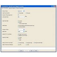
Shared Buffer with Embedded Addressing
When you turn on turn on Shared Buffer with Embedded Addressing, the POS-PHY
Level 4 MegaCore function consists of a shared buffer with embedded addressing,
and the transmitter processor logic.
The shared buffer is a single Atlantic FIFO buffer, where for each data word a tag is
carried containing the port number. There is no transmit scheduler provided with this
mode; the data is simply pulled from the buffer and transmitted in the same order it
was pushed in. This means that the order in which data bursts are transmitted on the
SPI-4.2 bus is dictated by the order in which the user logic writes data to the FIFO
buffer. The user logic is responsible for scheduling the transmit data and pushing it
into the transmitter buffers so that it is SPI-4.2 compliant (including ensuring that
burst sizes are properly maintained).
The shared FIFO buffer and the logic support up to 256 ports. If the Atlantic error
checking feature is turned on, the logic for error checking supports the number of
ports chosen as a parameter. The port width field remains fixed for 256 ports, and if
packets for ports beyond the number of ports parameter are pushed into the transmit
buffer, they are transmitted but are not checked for errors. All address bits are passed
through the buffer unaffected
The shared buffer with embedded addressing mode supports two different
backpressure mechanisms.
Slave-sink Atlantic interface on the user side
Configurable buffer size
Multiple clock domain support
Overflow error indication and FIFO buffer empty indication
Atlantic interface error checking
■
■
Missing or spurious start-of-packet (SOP)/end-of-packet (EOP) detection and
correction
Optional overflow handling
Chapter 5: Functional Description—Transmitter
December 2010 Altera Corporation
Block Description
Related parts for IPR-POSPHY4
Image
Part Number
Description
Manufacturer
Datasheet
Request
R

Part Number:
Description:
IP NIOS II MEGACORE RENEW
Manufacturer:
Altera
Datasheet:
Part Number:
Description:
IP CORE Renewal Of IP-XAUIPCS
Manufacturer:
Altera
Datasheet:

Part Number:
Description:
IP CORE Renewal Of IP-10GETHERNET
Manufacturer:
Altera
Datasheet:
Part Number:
Description:
IP CORE Renewal Of IP-ASI
Manufacturer:
Altera
Datasheet:

Part Number:
Description:
IP CORE Renewal Of IP-CIC
Manufacturer:
Altera
Datasheet:

Part Number:
Description:
IP CORE Renewal Of IP-CRC
Manufacturer:
Altera
Datasheet:
Part Number:
Description:
IP CORE Renewal Of IP-ED8B10B
Manufacturer:
Altera
Datasheet:

Part Number:
Description:
CPLD, EP610 Family, ECMOS Process, 300 Gates, 16 Macro Cells, 16 Reg., 16 User I/Os, 5V Supply, 35 Speed Grade, 24DIP
Manufacturer:
Altera Corporation
Datasheet:
Part Number:
Description:
CPLD, EP610 Family, ECMOS Process, 300 Gates, 16 Macro Cells, 16 Reg., 16 User I/Os, 5V Supply, 15 Speed Grade, 24DIP
Manufacturer:
Altera Corporation
Datasheet:
Part Number:
Description:
Manufacturer:
Altera Corporation
Datasheet: