LM49352RLX/NOPB National Semiconductor, LM49352RLX/NOPB Datasheet - Page 44
LM49352RLX/NOPB
Manufacturer Part Number
LM49352RLX/NOPB
Description
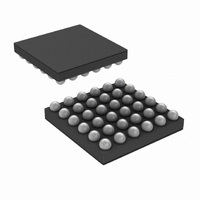
IC AMP AUDIO MONO D1.4W 36USMD
Manufacturer
National Semiconductor
Series
Boomer®, PowerWise®r
Type
Class Dr
Datasheet
1.LM49352RLNOPB.pdf
(110 pages)
Specifications of LM49352RLX/NOPB
Output Type
1-Channel (Mono) with Mono and Stereo Headphones
Max Output Power X Channels @ Load
1.4W x 1 @ 8 Ohm; 65mW x 2 @ 32 Ohm
Features
Depop, Differential Inputs, I²C, I²S, Microphone, Shutdown, Volume Control
Mounting Type
Surface Mount
Package / Case
36-MicroSMDxt
Lead Free Status / RoHS Status
Lead free / RoHS Compliant
Voltage - Supply
-
Other names
LM49352RLX
Available stocks
Company
Part Number
Manufacturer
Quantity
Price
Company:

Part Number:
LM49352RLX/NOPB
Manufacturer:
CYPRESS
Quantity:
562


www.national.com
19.0 Analog Mixer Control Registers
This register is used to control the LM49352's Analog Mixer:
Class D Loudspeaker Amplifier
The LM49352 features a filterless modulation scheme. The differential outputs of the device switch at 300kHz from V
When there is no input signal applied, the two outputs (LS+ and LS-) switch with a 50% duty cycle, with both outputs in phase.
Because the outputs of the LM49352 are differential, the two signals cancel each other. This results in no net voltage across the
speaker, thus there is no load current during an idle state, conserving power.
With an input signal applied, the duty cycle (pulse width) of the LM49352 outputs changes. For increasing output voltages, the duty
cycle of LS+ increases, while the duty cycle of LS- decreases. For decreasing output voltages, the converse occurs, the duty cycle
of LS- increases while the duty cycle of LS+ decreases. The difference between the two pulse widths yields the differential output
voltage.
Spread Spectrum Modulation
The LM49352 features a fitlerless spread spectrum modulation scheme that eliminates the need for output filters, ferrite beads or
chokes. The switching frequency varies by ±30% about a 300kHz center frequency, reducing the wideband spectral content,
improving EMI emissions radiated by the speaker and associated cables and traces. Where a fixed frequency class D exhibits
large amounts of spectral energy at multiples of the switching frequency, the spread spectrum architecture of the LM49352 spreads
that energy over a larger bandwidth. The cycle-to-cycle variation of the switching period does not affect the audio reproduction or
efficiency.
Class D Power Dissipation and Efficiency
In general terms, efficiency is considered to be the ratio of useful work output divided by the total energy required to produce it
with the difference being the power dissipated, typically, in the IC. The key here is “useful” work. For audio systems, the energy
delivered in the audible bands is considered useful including the distortion products of the input signal. Sub-sonic (DC) and super-
sonic components (>22kHz) are not useful. The difference between the power flowing from the power supply and the audio band
power being transduced is dissipated in the LM49352 and in the transducer load. The amount of power dissipation in the LM49352's
class D amplifier is very low. This is because the ON resistance of the switches used to form the output waveforms is typically less
than 0.25Ω. This leaves only the transducer load as a potential "sink" for the small excess of input power over audio band output
power. The LM49352 dissipates only a fraction of the excess power requiring no additional PCB area or copper plane to act as a
heat sink.
EMI/RFI Filtering
If system level PCB layout constraints require the LM49352’s Class D output bumps to be placed far away from the speaker or the
Class D output traces to be routed near EMI/RFI sensitive components, an external EMI/RFI filter should be used. A series ferrite
bead placed close to the Class D output bumps along with a shunt capacitor to ground placed close to the ferrite bead will reduce
the EMI/RFI emissions of the Class D amplifier’s switching outputs. The ferrite bead must be rated with a current rating high enough
to properly drive the loudspeaker. The ferrite bead that is rated for 1A or greater is recommended. The DC resistance of the ferrite
bead is another important specification that must be taken into consideration. A low DC resistance will minimize any power losses
dissipated by the EMI/RFI filter thereby preserving the power efficiency advantages of the Class D amplifier. Selecting a ferrite
bead with high DC resistance will decrease output power delivered to speaker and reduce the Class D amplifier’s efficiency. The
shunt capacitor needs to have low ESR. A 10pF ceramic capacitor with a X7R dielectric is recommended as a starting point. Care
needs to be taken to ensure that the value of the shunt capacitor does not exceed 47pF when using a low resistance ferrite bead
in order to prevent permanent damage to the low side FETs of the Class D output stage.
Bits
0
1
2
3
4
5
MONO_LS
DACR_LS
DACL_LS
AUX_LS
RSVD
RSVD
Field
The right DAC output is added to the loudspeaker output.
The left DAC output is added to the loudspeaker output.
Reserved
Reserved
The MONO input is added to the loudspeaker output.
The AUX input is added to the loudspeaker output.
TABLE 15. CLASS_D_OUTPUT (0x10h)
44
Description
DD
to GND.
Related parts for LM49352RLX/NOPB
Image
Part Number
Description
Manufacturer
Datasheet
Request
R

Part Number:
Description:
IC AMP AUDIO MONO D1.4W 36USMD
Manufacturer:
National Semiconductor
Datasheet:

Part Number:
Description:
Mono Class D Audio Codec Subsystem With Ground Referenced Headphone Amplifiers, Earpiece Driver, And Audio Dsp
Manufacturer:
National Semiconductor Corporation
Datasheet:

Part Number:
Description:
National Semiconductor [8-Bit D/A Converter]
Manufacturer:
National Semiconductor
Datasheet:
Part Number:
Description:
National Semiconductor [Media Coprocessor]
Manufacturer:
National Semiconductor
Datasheet:
Part Number:
Description:
Digitally Controlled Tone and Volume Circuit with Stereo Audio Power Amplifier, Microphone Preamp Stage and National 3D Sound
Manufacturer:
National Semiconductor
Datasheet:
Part Number:
Description:
Digitally Controlled Tone and Volume Circuit with Stereo Audio Power Amplifier, Microphone Preamp Stage and National 3D Sound
Manufacturer:
National Semiconductor
Datasheet:
Part Number:
Description:
AC97 Rev 2 Codec with Sample Rate Conversion and National 3D Sound
Manufacturer:
National Semiconductor
Part Number:
Description:
Manufacturer:
National Semiconductor
Datasheet:
Part Number:
Description:
Manufacturer:
National Semiconductor
Datasheet:
Part Number:
Description:
General Purpose, Low Voltage, Low Power, Rail-to-Rail Output Operational Amplifiers
Manufacturer:
National Semiconductor
Datasheet:
Part Number:
Description:
8-bit 20 MSPS flash A/D converter.
Manufacturer:
National Semiconductor
Datasheet:
Part Number:
Description:
Low Noise Quad Operational Amplifier
Manufacturer:
National Semiconductor
Datasheet:
Part Number:
Description:
Quad Differential Line Receivers
Manufacturer:
National Semiconductor
Datasheet: