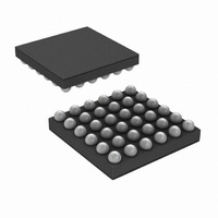
LM49352RLX/NOPB National Semiconductor, LM49352RLX/NOPB Datasheet - Page 70

LM49352RLX/NOPB
Manufacturer Part Number
LM49352RLX/NOPB
Description
IC AMP AUDIO MONO D1.4W 36USMD
Manufacturer
National Semiconductor
Series
Boomer®, PowerWise®r
Type
Class Dr
Datasheet
1.LM49352RLNOPB.pdf
(110 pages)
Specifications of LM49352RLX/NOPB
Output Type
1-Channel (Mono) with Mono and Stereo Headphones
Max Output Power X Channels @ Load
1.4W x 1 @ 8 Ohm; 65mW x 2 @ 32 Ohm
Features
Depop, Differential Inputs, I²C, I²S, Microphone, Shutdown, Volume Control
Mounting Type
Surface Mount
Package / Case
36-MicroSMDxt
Lead Free Status / RoHS Status
Lead free / RoHS Compliant
Voltage - Supply
-
Other names
LM49352RLX
Available stocks
Company
Part Number
Manufacturer
Quantity
Price
Company:
Part Number:
LM49352RLX/NOPB
Manufacturer:
CYPRESS
Quantity:
562
www.national.com
Bits
Bits
2:0
3:0
3
4
5
6
7
4
SOURCE_RSEL
SOURCE_LSEL
NOISE_FLOOR
SOURCE_OVR
ADC_SAMPLE
STEREO LINK
NG_ENB
LIMITER
Field
Field
This programs the timers on the ALC with the closest sample rate of the ADC.
If set, the circuit will never apply gain to the signal, no matter how small, but it will attenuate the
signal as soon as it reaches target and release it at the decay rate, once signal level reduces below
target. The I
will apply. Care should be taken when choosing the optimum I
the Limiter.
If set, the ALC circuit uses the stereo average of the input signals to control the gain of the stereo
output. This maintains stereo imaging. If this bit is cleared, then both channels operate as dual
mono.
If both SOURCE_OVR and this bit is set, the right ADC ALC channel will be active.
If both SOURCE_OVR and this bit is set, the left ADC ALC channel will be active.
If set, the active channel of the ADC ALC is determined by SOURCE_RSEL and SOURCE_LSEL.
If cleared, the active channel of the ADC ALC is determined by the selected input to the ADC.
MONO enables left ALC, AUX enables right ALC, MIC enables left and / or right ALC depending
on which ADC channel MIC is selected to.
This sets the anticipated noise floor. Signals lower than the noise floor specified will be gated from
the ALC to avoid noise pumping.
This enables the Noise Gate.
2
C gain setting (at the time the LIMITER is enabled) is the maximum gain that the ALC
TABLE 46. ADC_ALC_1 (0x81h)
TABLE 47. ADC_ALC_2 (0x82h)
NOISE_FLOOR
ADC_SAMPLE
0000
0001
0010
0011
0100
0101
0110
0111
1000
1001
1010
1011
1100
1101
1110
1111
000
001
010
011
100
101
110
111
70
Description
Description
2
C gain setting whenever enabling
Expected ADC f
Noise Floor (dB)
192kHz
12kHz
16kHz
24kHz
32kHz
48kHz
96kHz
8kHz
–39
–42
–45
–48
–51
–54
–57
–60
–63
–66
–69
–72
–75
–78
–81
–84
S


