LM49352RLX/NOPB National Semiconductor, LM49352RLX/NOPB Datasheet - Page 51
LM49352RLX/NOPB
Manufacturer Part Number
LM49352RLX/NOPB
Description
IC AMP AUDIO MONO D1.4W 36USMD
Manufacturer
National Semiconductor
Series
Boomer®, PowerWise®r
Type
Class Dr
Datasheet
1.LM49352RLNOPB.pdf
(110 pages)
Specifications of LM49352RLX/NOPB
Output Type
1-Channel (Mono) with Mono and Stereo Headphones
Max Output Power X Channels @ Load
1.4W x 1 @ 8 Ohm; 65mW x 2 @ 32 Ohm
Features
Depop, Differential Inputs, I²C, I²S, Microphone, Shutdown, Volume Control
Mounting Type
Surface Mount
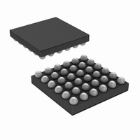
Package / Case
36-MicroSMDxt
Lead Free Status / RoHS Status
Lead free / RoHS Compliant
Voltage - Supply
-
Other names
LM49352RLX
Available stocks
Company
Part Number
Manufacturer
Quantity
Price
Company:

Part Number:
LM49352RLX/NOPB
Manufacturer:
CYPRESS
Quantity:
562


Headphone Detection Circuit
The LM49352 features a headphone detection circuit (HDC) that automatically enables the headphone amplifier whenever the
insertion of a headphone plug is detected and disables the headphone amplifier during the removal of a headphone plug. The HDC
optimizes power management by automatically disabling any output amplifier that is not in use. The HDC eliminates the necessity
of polling the I
2
C bus for status changes. However, since the HDC requires the use of the GPIO pin, the PORT2_SDO functionality
sensing is required.
The HDC requires a headphone jack with a normally closed mechanical switch and a pullup resistor, R
, tied between the me-
PU
chanical switch and I/O_V
(Refer to Figure 14). Choosing a R
value of at least 500kΩ ensures minimal current draw through
DD
PU
the pullup resistor. When the headphone amplifier is disabled, an internal 50kΩ pulldown, R
, is connected to each headphone
PD
amplifier output. Without the presence of a headphone plug, the headphone jack’s mechanical switch is closed thereby connecting
the right headphone amplifier output to R
. The GPIO pin detects a logic low level due to the voltage division between R
and
PU
PU
R
. When the GPIO pin is set to HPSENSE mode, a logic low voltage reading causes the HDC to disable the headphone amplifier.
PD
When a headphone plug is inserted, the mechanical connection between R
and R
is broken, resulting in a logic high level
PU
PD
detected by the GPIO pin. A logic high voltage reading causes the HDC to enable the headphone amplifier.
The HDC has four modes of operation that automatically enable/disable different combinations of the audio output amplifiers
contained within the LM49352. Having the choice of four different HDC settings maximizes power management flexibility to suit a
particular application. Please refer to the HP_SENSE (reg 0x1Bh) register table for a detailed discussion on the different HDC
modes of operation.
30072793
FIGURE 15. Application Circuit for Headphone Detection
51
www.national.com
Related parts for LM49352RLX/NOPB
Image
Part Number
Description
Manufacturer
Datasheet
Request
R

Part Number:
Description:
IC AMP AUDIO MONO D1.4W 36USMD
Manufacturer:
National Semiconductor
Datasheet:

Part Number:
Description:
Mono Class D Audio Codec Subsystem With Ground Referenced Headphone Amplifiers, Earpiece Driver, And Audio Dsp
Manufacturer:
National Semiconductor Corporation
Datasheet:

Part Number:
Description:
National Semiconductor [8-Bit D/A Converter]
Manufacturer:
National Semiconductor
Datasheet:
Part Number:
Description:
National Semiconductor [Media Coprocessor]
Manufacturer:
National Semiconductor
Datasheet:
Part Number:
Description:
Digitally Controlled Tone and Volume Circuit with Stereo Audio Power Amplifier, Microphone Preamp Stage and National 3D Sound
Manufacturer:
National Semiconductor
Datasheet:
Part Number:
Description:
Digitally Controlled Tone and Volume Circuit with Stereo Audio Power Amplifier, Microphone Preamp Stage and National 3D Sound
Manufacturer:
National Semiconductor
Datasheet:
Part Number:
Description:
AC97 Rev 2 Codec with Sample Rate Conversion and National 3D Sound
Manufacturer:
National Semiconductor
Part Number:
Description:
Manufacturer:
National Semiconductor
Datasheet:
Part Number:
Description:
Manufacturer:
National Semiconductor
Datasheet:
Part Number:
Description:
General Purpose, Low Voltage, Low Power, Rail-to-Rail Output Operational Amplifiers
Manufacturer:
National Semiconductor
Datasheet:
Part Number:
Description:
8-bit 20 MSPS flash A/D converter.
Manufacturer:
National Semiconductor
Datasheet:
Part Number:
Description:
Low Noise Quad Operational Amplifier
Manufacturer:
National Semiconductor
Datasheet:
Part Number:
Description:
Quad Differential Line Receivers
Manufacturer:
National Semiconductor
Datasheet: