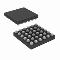
LM49352RLX/NOPB National Semiconductor, LM49352RLX/NOPB Datasheet - Page 68

LM49352RLX/NOPB
Manufacturer Part Number
LM49352RLX/NOPB
Description
IC AMP AUDIO MONO D1.4W 36USMD
Manufacturer
National Semiconductor
Series
Boomer®, PowerWise®r
Type
Class Dr
Datasheet
1.LM49352RLNOPB.pdf
(110 pages)
Specifications of LM49352RLX/NOPB
Output Type
1-Channel (Mono) with Mono and Stereo Headphones
Max Output Power X Channels @ Load
1.4W x 1 @ 8 Ohm; 65mW x 2 @ 32 Ohm
Features
Depop, Differential Inputs, I²C, I²S, Microphone, Shutdown, Volume Control
Mounting Type
Surface Mount
Package / Case
36-MicroSMDxt
Lead Free Status / RoHS Status
Lead free / RoHS Compliant
Voltage - Supply
-
Other names
LM49352RLX
Available stocks
Company
Part Number
Manufacturer
Quantity
Price
Company:
Part Number:
LM49352RLX/NOPB
Manufacturer:
CYPRESS
Quantity:
562
ALC Overview
The Automatic Level Control (ALC) system can be used to regulate the audio output level to a user defined target level. The ALC
feature is especially useful whenever the level of the audio input is unknown, unpredictable, or has a large dynamic range. The
main purpose of the ALC is to optimize the dynamic range of the audio input to audio output path.
There are two separate and independent ALC circuits in the LM49352. One of the ALC circuits is located within the DAC DSP
effects block. The other ALC circuit is integrated into the ADC DSP effects block. The DAC ALC controls the DAC digital gain. The
ADC ALC controls the mono/auxiliary input amplifier gain or microphone preamplifier gain. The dual ALCs can be used to regulate
the level of the analog (AUX, MONO, MIC) and digital (Port1 Data In, Port2 Data In) audio inputs. The ALC regulated output can
be routed to any of the LM49352’s amplifier outputs for playback. The ALC regulated output can also be routed to Audio Port1 or
Audio Port2 for digital data transmission via I
2
S or PCM.
Only audio inputs that are considered signals (rather than noise) are sent to the ALC’s peak detector block. The peak detector
compares the level of the audio input versus the ALC target level (TARGET_LEVEL). Signals lower than the target level will be
amplified and signals higher than the target level will be attenuated. Any audio input that is lower than the level specified by the
noise floor level (NOISE_FLOOR) will be considered as noise and will be gated from the ALC’s peak detector in order to avoid
noise pumping. So it is important to set NOISE_FLOOR to correlate with the signal to noise ratio of the corresponding audio path.
In some instances (ie. Conference calls), it may be desirable to mute audio input signals that consist solely of background noise
from the audio output. This is accomplished by enabling the ALC’s noise gate (NG_ENB). When the noise gate is enabled, signals
lower than the noise floor level will be muted from the audio output.
If the audio input signal is below the target level, the ALC will increase the gain of the corresponding volume control until the signal
reaches the target level. The rate at which the ALC performs gain increases is known as decay rate (DECAY RATE). But before
each ALC gain increase the ALC must wait a predetermined amount of time (HOLD TIME). If the audio input signal is above the
target level, the ALC will decrease the gain of the corresponding volume control until the signal reaches the target level. The rate
at which the ALC performs attenuation is known as attack rate (ATTACK RATE). The ALC’s peak detector tracks increases in
audio input signal amplitude instantaneously, but tracks decreases in audio input signal amplitude at programmable rate (PEAK
DECAY TIME). ATTACK RATE, DECAY RATE, HOLD TIME, and PEAK DECAY TIME are fully adjustable which allows flexible
operation of the ALC circuit. The ALC’s timers are based on the sample rate of the DAC or ADC, so the closest corresponding
sample rate must be programmed into the DAC SAMPLE setting (for DAC ALC) or the ADC SAMPLE (for ADC ALC).
30072791
FIGURE 23. ALC Example
www.national.com
68


