LM49352RLX/NOPB National Semiconductor, LM49352RLX/NOPB Datasheet - Page 7
LM49352RLX/NOPB
Manufacturer Part Number
LM49352RLX/NOPB
Description
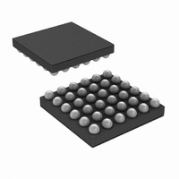
IC AMP AUDIO MONO D1.4W 36USMD
Manufacturer
National Semiconductor
Series
Boomer®, PowerWise®r
Type
Class Dr
Datasheet
1.LM49352RLNOPB.pdf
(110 pages)
Specifications of LM49352RLX/NOPB
Output Type
1-Channel (Mono) with Mono and Stereo Headphones
Max Output Power X Channels @ Load
1.4W x 1 @ 8 Ohm; 65mW x 2 @ 32 Ohm
Features
Depop, Differential Inputs, I²C, I²S, Microphone, Shutdown, Volume Control
Mounting Type
Surface Mount
Package / Case
36-MicroSMDxt
Lead Free Status / RoHS Status
Lead free / RoHS Compliant
Voltage - Supply
-
Other names
LM49352RLX
Available stocks
Company
Part Number
Manufacturer
Quantity
Price
Company:

Part Number:
LM49352RLX/NOPB
Manufacturer:
CYPRESS
Quantity:
562


1.0 General Description ......................................................................................................................... 1
2.0 Applications .................................................................................................................................... 1
3.0 Key Specifications ........................................................................................................................... 1
4.0 Features ........................................................................................................................................ 1
5.0 LM49352 Overview .......................................................................................................................... 2
6.0 Typical Application ........................................................................................................................... 3
7.0 Connection Diagrams ..................................................................................................................... 10
8.0 Absolute Maximum Ratings ............................................................................................................ 13
9.0 Operating Ratings ......................................................................................................................... 13
10.0 Electrical Characteristics: A_V
11.0 Typical Performance Characteristics .............................................................................................. 19
12.0 System Control ............................................................................................................................ 29
13.0 Device Register Map .................................................................................................................... 32
14.0 Basic PMC Setup Register ............................................................................................................ 36
15.0 PMC Clocks Register ................................................................................................................... 37
16.0 PMC Clock Divide Register ........................................................................................................... 37
17.0 LM49352 Clock Network .............................................................................................................. 38
18.0 PLL Setup Registers .................................................................................................................... 40
19.0 Analog Mixer Control Registers ..................................................................................................... 44
20.0 ADC Control Registers ................................................................................................................. 53
21.0 DAC Control Registers ................................................................................................................. 55
22.0 Digital Mixer Control Registers ...................................................................................................... 56
23.0 Audio Port Control Registers ......................................................................................................... 60
24.0 Digital Effects Engine ................................................................................................................... 66
25.0 DAC Effects Registers .................................................................................................................. 87
26.0 GPIO Registers ......................................................................................................................... 102
27.0 Schematic Diagram .................................................................................................................... 104
28.0 Demonstration Board Layout ....................................................................................................... 105
29.0 Revision History ........................................................................................................................ 108
30.0 Physical Dimensions .................................................................................................................. 109
FIGURE 1. LM49352 Block Diagram ............................................................................................................. 2
FIGURE 2. Example Application in Multimedia Phone with Dedicated Earpiece Speaker and Mono Loudspeaker ................ 3
FIGURE 3. Example Application in Multimedia Phone Using Multiple Media Sources .................................................. 4
FIGURE 4. Example Application in a Multimedia Phone with Stereo Loudspeaker ...................................................... 5
FIGURE 5. Example Application in a Portable Media Player with Stereo Loudspeakers ................................................ 6
FIGURE 6. I
FIGURE 7. I
FIGURE 8. I
FIGURE 9. Example I
FIGURE 10. Example I
FIGURE 11. I
FIGURE 12. Internal Clock Network ............................................................................................................. 39
FIGURE 13. PLL Loop
FIGURE 14. EMI/RFI Filter for the Class D Amplifier ......................................................................................... 45
FIGURE 15. Application Circuit for Headphone Detection ................................................................................... 51
FIGURE 16. Digital Mixer .......................................................................................................................... 56
FIGURE 17. I
FIGURE 18. Left Justified Data Format (24 bit example) .................................................................................... 60
FIGURE 19. Right Justified Data Format (24 bit example) .................................................................................. 60
FIGURE 20. PCM Serial Data Format (16 bit example) ...................................................................................... 60
FIGURE 21. ADC DSP Effects Chain ........................................................................................................... 66
FIGURE 22. DAC DSP Effects Chain ........................................................................................................... 66
FIGURE 23. ALC Example ........................................................................................................................ 68
FIGURE 24. ALC Limiter ........................................................................................................................... 69
FIGURE 25. Audio Compressor Effect .......................................................................................................... 82
FIGURE 26. Soft Knee Example with Compression Ratio Setting of 1:3.4 ............................................................... 83
7.1 PIN TYPE DEFINITIONS ........................................................................................................ 12
12.1 I
12.2 I
12.3 I
12.4 TRANSFERRING DATA ........................................................................................................ 29
12.5 I
2
2
2
2
2
2
2
C SIGNALS ....................................................................................................................... 29
C DATA VALIDITY ............................................................................................................. 29
C START AND STOP CONDITIONS ..................................................................................... 29
C TIMING PARAMETERS .................................................................................................. 31
C Signals: Data Validity ............................................................................................................ 29
C Start and Stop Conditions ...................................................................................................... 29
C Chip Address ..................................................................................................................... 29
2
2
C Timing Diagram ................................................................................................................. 30
S Serial Data Format (24 bit example) ........................................................................................ 60
2
C Write Cycle ............................................................................................................ 30
2
C Read Cycle .......................................................................................................... 30
............................................................................................................................ 40
DD
= LS_V
Table of Contents
List of Figures
DD
= 3.3V; HP_V
7
DD
= D_V
DD
= I/O_V
DD
= 1.8V ...................... 13
www.national.com
Related parts for LM49352RLX/NOPB
Image
Part Number
Description
Manufacturer
Datasheet
Request
R

Part Number:
Description:
IC AMP AUDIO MONO D1.4W 36USMD
Manufacturer:
National Semiconductor
Datasheet:

Part Number:
Description:
Mono Class D Audio Codec Subsystem With Ground Referenced Headphone Amplifiers, Earpiece Driver, And Audio Dsp
Manufacturer:
National Semiconductor Corporation
Datasheet:

Part Number:
Description:
National Semiconductor [8-Bit D/A Converter]
Manufacturer:
National Semiconductor
Datasheet:
Part Number:
Description:
National Semiconductor [Media Coprocessor]
Manufacturer:
National Semiconductor
Datasheet:
Part Number:
Description:
Digitally Controlled Tone and Volume Circuit with Stereo Audio Power Amplifier, Microphone Preamp Stage and National 3D Sound
Manufacturer:
National Semiconductor
Datasheet:
Part Number:
Description:
Digitally Controlled Tone and Volume Circuit with Stereo Audio Power Amplifier, Microphone Preamp Stage and National 3D Sound
Manufacturer:
National Semiconductor
Datasheet:
Part Number:
Description:
AC97 Rev 2 Codec with Sample Rate Conversion and National 3D Sound
Manufacturer:
National Semiconductor
Part Number:
Description:
Manufacturer:
National Semiconductor
Datasheet:
Part Number:
Description:
Manufacturer:
National Semiconductor
Datasheet:
Part Number:
Description:
General Purpose, Low Voltage, Low Power, Rail-to-Rail Output Operational Amplifiers
Manufacturer:
National Semiconductor
Datasheet:
Part Number:
Description:
8-bit 20 MSPS flash A/D converter.
Manufacturer:
National Semiconductor
Datasheet:
Part Number:
Description:
Low Noise Quad Operational Amplifier
Manufacturer:
National Semiconductor
Datasheet:
Part Number:
Description:
Quad Differential Line Receivers
Manufacturer:
National Semiconductor
Datasheet: