CDB5467U Cirrus Logic Inc, CDB5467U Datasheet - Page 42
CDB5467U
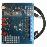
Manufacturer Part Number
CDB5467U
Description
BOARD EVAL FOR CS5467 ADC
Manufacturer
Cirrus Logic Inc
Type
A/Dr
Specifications of CDB5467U
Main Purpose
Power Management, Energy/Power Meter
Embedded
Yes, MCU, 8-Bit
Utilized Ic / Part
CS5467
Primary Attributes
Watt-Hour Meter
Secondary Attributes
Graphical User Interface, SPI™ & USB Interfaces
Product
Data Conversion Development Tools
Maximum Clock Frequency
4 MHz
Interface Type
USB
Supply Voltage (max)
5 V
Supply Voltage (min)
3.3 V
For Use With/related Products
CS5467
Lead Free Status / RoHS Status
Contains lead / RoHS non-compliant
Lead Free Status / RoHS Status
Lead free / RoHS Compliant, Contains lead / RoHS non-compliant
Other names
598-1555
CDB-5467U
CDB-5467U


10. E
The CS5467 can accept commands from a serial
E
host microcontroller. A high level (logic 1) on the MODE
input indicates that an E
makes the CS and SCLK pins become driven outputs.
After reset and after running the initialization program,
the CS5467 begins reading commands from the con-
nected E
10.1 E
A typical connection between the CS5467 and a
E
The CS5467 asserts CS (logic 0), clocks SCLK, and
sends Read commands to the E
Command format is identical to microcontroller mode,
except the CS5467 will not attempt to write to the EE-
PROM device. The command sequence stops when the
STOP bit in the Control register ( Ctrl ) is written by the
command sequence.
Figure 13
would be made to a calibration device, such as a note-
book computer, handheld calibrator, or tester during
meter assembly, The calibrator or tester can be used to
control the CS5467 during calibration and program the
required values into the E
42
Figure 13. Typical Interface of E
2
2
5 K
PROM connected to the serial interface instead of a
PROM is shown in
VD
+
2
PROM OPERATION
2
2
MODE
PROM Configuration
PROM.
CS5467
also shows the external connections that
SCLK
SDO
SDI
CS
E1
E2
Connector to Calibrator
Figure
2
2
PROM.
PROM is connected. This
13.
Pulse Output
5 K
Counter
2
PROM on SDO.
2
PROM to CS5467
SO
SI
SCK
CS
EEPROM
10.2 E
The EEPROM code should do the following:
1. Set any Configuration or Control register bits, such as
2. Write any calibration data to gain and offset registers.
3. Set energy output pulse width, rate, and formats.
4. Execute a Continuous Conversion command.
5. Set the STOP bit in the Control register (last).
Below is an example E
10.3 Which E
Several industry-standard serial E
with the CS5467. Some are listed below:
•
•
•
These serial E
mand (00000011) in order to perform a memory read.
The CS5467 has been hardware programmed to trans-
mit this 8-bit command to the E
HPF enables and phase compensation settings.
- 7E 00 00 01
- 60 00 01 E0
- 42 7F C4 A9
- 46 FF B2 53
- 50 7F C4 A9
- 54 FF B2 53
- 7E 00 00 00
- 74 00 00 04
- E8
- 78 00 01 00
Atmel AT25010, AT25020 or AT25040
National Semiconductor NM25C040M8 or NM25020M8
Xicor X25040SI
Change to page 1.
Write Modes Register, turn high-pass filters on.
Write value of 0x7FC4A9 to I1
Write value of 0xFFB253 to V1
Write value of 0x7FC4A9 to I2
Write value of 0xFFB253 to V2
Change to page 0.
Set LSD bit to 1 in the Mask register.
Start continuous conversions
Write STOP bit to the Control register ( Ctrl ) to
terminate E
2
PROM Code
2
PROMs expect a specific 8-bit com-
2
2
PROM command sequence.
PROMs Can Be Used?
2
PROM code set.
2
PROM after reset.
2
PROMs can be used
GAIN
GAIN
GAIN
GAIN
register.
register.
register.
register.
CS5467
DS714F1
Related parts for CDB5467U
Image
Part Number
Description
Manufacturer
Datasheet
Request
R

Part Number:
Description:
Development Kit
Manufacturer:
Cirrus Logic Inc
Datasheet:
Part Number:
Description:
Development Kit
Manufacturer:
Cirrus Logic Inc
Datasheet:


Part Number:
Description:
High-efficiency PFC + Fluorescent Lamp Driver Reference Design
Manufacturer:
Cirrus Logic Inc
Datasheet:
Part Number:
Description:
Development Kit
Manufacturer:
Cirrus Logic Inc
Datasheet:
Part Number:
Description:
Development Kit
Manufacturer:
Cirrus Logic Inc
Datasheet:

Part Number:
Description:
Development Kit
Manufacturer:
Cirrus Logic Inc
Datasheet:
Part Number:
Description:
Development Kit
Manufacturer:
Cirrus Logic Inc
Datasheet:
Part Number:
Description:
Development Kit
Manufacturer:
Cirrus Logic Inc
Datasheet:
Part Number:
Description:
Development Kit
Manufacturer:
Cirrus Logic Inc
Datasheet:

Part Number:
Description:
EVALUATION BOARD FOR CS8427
Manufacturer:
Cirrus Logic Inc
Datasheet:

Part Number:
Description:
BOARD EVAL FOR CS8416 RCVR
Manufacturer:
Cirrus Logic Inc
Datasheet:

Part Number:
Description:
EVALUATION BOARD FOR CS8420
Manufacturer:
Cirrus Logic Inc
Datasheet:

Part Number:
Description:
KIT DEVELOPMENT EP9315 ARM9
Manufacturer:
Cirrus Logic Inc
Datasheet:

Part Number:
Description:
KIT DEVELOPMENT EP9302 ARM9
Manufacturer:
Cirrus Logic Inc
Datasheet: