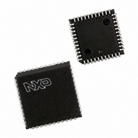
P87C591VFA/00,512 NXP Semiconductors, P87C591VFA/00,512 Datasheet - Page 64

P87C591VFA/00,512
Manufacturer Part Number
P87C591VFA/00,512
Description
IC 80C51 MCU 16K OTP 44-PLCC
Manufacturer
NXP Semiconductors
Series
87Cr
Datasheet
1.P87C591VFA00512.pdf
(160 pages)
Specifications of P87C591VFA/00,512
Core Processor
8051
Core Size
8-Bit
Speed
12MHz
Connectivity
CAN, EBI/EMI, I²C, UART/USART
Peripherals
POR, PWM, WDT
Number Of I /o
32
Program Memory Size
16KB (16K x 8)
Program Memory Type
OTP
Ram Size
512 x 8
Voltage - Supply (vcc/vdd)
4.75 V ~ 5.25 V
Data Converters
A/D 6x10b
Oscillator Type
Internal
Operating Temperature
-40°C ~ 85°C
Package / Case
44-PLCC
Processor Series
P87C5x
Core
80C51
Data Bus Width
8 bit
Data Ram Size
512 B
Interface Type
CAN, I2C, UART
Maximum Clock Frequency
12 MHz
Number Of Programmable I/os
32
Number Of Timers
3
Maximum Operating Temperature
+ 85 C
Mounting Style
SMD/SMT
3rd Party Development Tools
PK51, CA51, A51, ULINK2
Minimum Operating Temperature
- 40 C
On-chip Adc
10 bit, 6 Channel
Lead Free Status / RoHS Status
Lead free / RoHS Compliant
Eeprom Size
-
Lead Free Status / Rohs Status
Details
Other names
568-1256-5
935268182512
P87C591VFAA
935268182512
P87C591VFAA
Available stocks
Company
Part Number
Manufacturer
Quantity
Price
Company:
Part Number:
P87C591VFA/00,512
Manufacturer:
TI
Quantity:
8
Company:
Part Number:
P87C591VFA/00,512
Manufacturer:
NXP Semiconductors
Quantity:
10 000
Philips Semiconductors
With the baud rate generator as clock source for the serial
port in Mode 1 and Mode 3, the baud rate of can be
determined as follows:
Mode 1, 3 baud rate =
Baud rate generator overflow rate =
Table 47 lists baud rates and how they can be obtained
from the Internal Baud Rate Generator.
14.3.8
In Mode 1 and 3 of the serial port also timer 1 can be used
for generating baud rates. Then the baud rate is
determined by the timer 1 overflow rate and the value of
SMOD1 as follows:
Table 44 Serial Port Control Register SCON (address)
Table 45 Description of S0PSH and S0PSL bits
2000 Jul 26
2
S0PS: Baud Rate Generator Prescaler load value
Single-chip 8-bit microcontroller with CAN controller
12
BIT
SM0
- S0PS with S0PS = S0PSH.3 - 0, S0PSL.7 - 0.
7
6
5
4
3
2
1
0
7
-------------------------------------------------------------------------------------------------------- -
32 (baud rate generator overflow rate)
U
SING
2
SMOD1
T
SYMBOL
IMER
REN
SM0
SM1
SM2
RB8
TB8
SM1
RI
TI
6
1
osciillator frequency
TO
G
ENERATE
See Table 46.
See Table 46.
Enables the multiprocessor communication feature in Modes 2 and 3. In Mode 2 or
3, if SM2 is set to 1, then RI will not be activated if the received 9
Mode 1, if SM2 = 1 then RI will not be activated if a valid stop bit was not received. In
Mode 0, SM2 should be 0.
Enables serial reception. Set by software to enable reception. Clear by software to
disable reception.
The 9
desired.
In Modes 2 and 3, is the 9
the stop bit that was received. In Mode 0, RB8 is not used.
Transmit interrupt flag. Set by hardware at the end of the 8
the beginning of the stop bit in the other modes, in any serial transmission. Must be
cleared by software.
Receive interrupt flag. Set by hardware at the end of the 8
halfway through the stop bit time in the other modes, in any serial reception (except see
SM2). Must be cleared by software.
SM2
th
5
B
data bit that will be transmitted in Modes 2 and 3. Set or clear by software as
AUD
R
ATES
REN
4
th
64
data bit that was received. In Mode 1, if SM2 = 0, RB8 is
The Timer 1 interrupt is usually disabled in this application.
Timer 1 itself can be configured for either “timer” or
“counter” operation, and in any of its operating modes. In
most typical applications, it is configured for “timer”
operation in the auto-reload (high nibble of TMOD =
0010B). In this case the baud rate is given by the formula:
Very low baud rates can be achieved with Timer 1 if
leaving the Timer 1 interrupt enabled, configuring the timer
to run as 16-bit timer (high nibble of TMOD = 0001B), and
using the Timer 1 interrupt for a 16-bit software reload.
Table 49 lists lower baud rates and how they can be
obtained from Timer 1.
Mode 1, 3 baud rate
Mode1 3 baud rate =
TB8
3
DESCRIPTION
RB8
2
=
2
--------------------
2
------------------------------------------------------------------------------ -
SMOD1
SMOD1
32
32 6
th
th
bit time in Mode 0, or
bit time in Mode 0, or at
Preliminary Specification
th
(timer 1 overflow rate)
TI
1
oscillator frequency
data bit (RB8) is 0. In
256
P8xC591
–
TH1
RI
0


