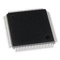
MB95F126JBPFR-GE1 Fujitsu, MB95F126JBPFR-GE1 Datasheet - Page 36

MB95F126JBPFR-GE1
Manufacturer Part Number
MB95F126JBPFR-GE1
Description
MCU, 8-BIT, 8FX, 32K FLASH, QFP100
Manufacturer
Fujitsu
Datasheet
1.MB95F126JBPF-GE1.pdf
(80 pages)
Specifications of MB95F126JBPFR-GE1
Controller Family/series
F2MC-8FX
No. Of I/o's
87
Ram Memory Size
1KB
Cpu Speed
16.25MHz
No. Of Timers
7
No. Of Pwm
RoHS Compliant
Core Size
8bit
Program Memory Size
32KB
Oscillator Type
External Only
MB95120MB Series
36
2. Recommended Operating Conditions
*1 : The values vary with the operating frequency, machine clock or analog guarantee range.
*2 : When the low voltage detection reset is used, reset occurs while the low voltage is detected. For details on
*3 : Use a ceramic capacitor or a capacitor with equivalent frequency characteristics. A bypass capacitor of V
WARNING: The recommended operating conditions are required in order to ensure the normal operation of
Power supply
voltage
Power supply
voltage for LCD
A/D converter
reference
input voltage
Smoothing
capacitor
Operating
temperature
• C pin connection diagram
Parameter
Low voltage detection, see "(9) Low Voltage Detection" in "4. AC Characteristics".
pin must have a capacitor value higher than C
below.
the semiconductor device. All of the device's electrical characteristics are warranted when the
device is operated within these ranges.
Always use semiconductor devices within their recommended operating condition ranges.
Operation outside these ranges may adversely affect reliability and could result in device failure.
No warranty is made with respect to uses, operating conditions, or combinations not represented
on the data sheet. Users considering application outside the listed conditions are advised to contact
their representatives beforehand.
V0 to V3
Symbol
AV
AVR
V
C
T
CC
S
A
CC
,
Condi-
tion
⎯
C
S
2.42*
Min
− 40
V
2.3
2.7
2.3
4.0
0.1
+ 5
SS
1,
S
*
Value
. For connection of smoothing capacitor C
2
5.5*
AV
+ 105
Max
+ 35
V
5.5
5.5
5.5
1.0
CC
C
CC
1
Unit
μF
°C Other than MB95FV100D-103
°C MB95FV100D-103
V
V
V
In normal operating
Hold condition in
STOP mode
In normal operating
Hold condition in
STOP mode
The range of liquid crystal power supply
(The optimal value depends on liquid
crystal display elements used.)
*3
Remarks
S
, refer to the diagram
Other than
MB95FV100D-103
MB95FV100D-103
(AV
SS
DS07-12610-5E
= V
SS
= 0.0 V)
CC


