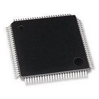
MB95F126JBPFR-GE1 Fujitsu, MB95F126JBPFR-GE1 Datasheet - Page 60

MB95F126JBPFR-GE1
Manufacturer Part Number
MB95F126JBPFR-GE1
Description
MCU, 8-BIT, 8FX, 32K FLASH, QFP100
Manufacturer
Fujitsu
Datasheet
1.MB95F126JBPF-GE1.pdf
(80 pages)
Specifications of MB95F126JBPFR-GE1
Controller Family/series
F2MC-8FX
No. Of I/o's
87
Ram Memory Size
1KB
Cpu Speed
16.25MHz
No. Of Timers
7
No. Of Pwm
RoHS Compliant
Core Size
8bit
Program Memory Size
32KB
Oscillator Type
External Only
MB95120MB Series
60
(Continued)
*1 : R, C : Pull-up resistor and load capacitor of the SCL and SDA lines.
*2 : • Refer to “ (2) Source Clock/Machine Clock” for t
Stop condition
detection
Restart condition
detection condition
Bus free time
Data hold time
Data setup time
Data hold time
Data setup time
SDA↓→SCL↑
(at wakeup function)
• m is CS4 bit and CS3 bit (bit 4 and bit 3) of I
• n is CS2 bit to CS0 bit (bit 2 to bit 0) of I
• Actual timing of I
• Standard-mode :
• Fast-mode :
Parameter
ICCR0 register.
m and n can be set at the range : 0.9 MHz < t
Setting of m and n determines the machine clock that can be used below.
m and n can be set at the range : 3.3 MHz < t
Setting of m and n determines the machine clock that can be used below.
(m, n) = (1, 8)
(m, n) = (1, 22) , (5, 4) , (6, 4) , (7, 4) , (8, 4) : 0.9 MHz < t
(m, n) = (1, 38) , (5, 8) , (6, 8) , (7, 8) , (8, 8) : 0.9 MHz < t
(m, n) = (1, 98)
(m, n) = (1, 8)
(m, n) = (1, 22) , (5, 4)
(m, n) = (6, 4)
2
C is determined by m and n values set by the machine clock (t
Sym-
t
t
t
t
t
t
t
SU;STO
HD;DAT
HD;DAT
SU;STA
SU;DAT
SU;DAT
WAKE-
bol
t
BUF
UP
name
SDA0
SDA0
SDA0
SDA0
SDA0
SDA0
SDA0
SDA0
SCL0
SCL0
SCL0
SCL0
SCL0
SCL0
SCL0
SCL0
Pin
R = 1.7 kΩ,
C = 50 pF*
Condition
2
C clock control register (ICCR) .
(V
CC
1
2
C clock control register (ICCR) .
MCLK
MCLK
= 5.0 V ± 10%, AV
t
LOW
MCLK
stabilization
2 t
2 t
2 t
2 t
2 t
wait time +
Oscillation
t
(machine clock) < 10 MHz.
(machine clock) < 10 MHz.
− 3 t
MCLK
MCLK
MCLK
MCLK
MCLK
MCLK
.
: 0.9 MHz < t
: 0.9 MHz < t
: 3.3 MHz < t
: 3.3 MHz < t
: 3.3 MHz < t
Min
0
MCLK
− 20
− 20
− 20
− 20
− 20
− 20
Value*
− 20
2
SS
MCLK
MCLK
MCLK
MCLK
MCLK
MCLK
MCLK
= V
Max
⎯
⎯
⎯
⎯
⎯
⎯
⎯
⎯
≤ 1 MHz
≤ 2 MHz
≤ 4 MHz
≤ 10 MHz
≤ 4 MHz
≤ 8 MHz
≤ 10 MHz
SS
= 0.0 V, T
Unit
ns
ns
ns
ns
ns
ns
ns
ns
MCLK
A
) and CS4 to CS0 of
= −40 °C to + 105 °C)
Undetected when 1
t
reception
Undetected when 1
t
reception
At reception
At slave transmission
mode
At slave transmission
mode
At reception
At reception
MCLK
MCLK
is used at
is used at
Remarks
DS07-12610-5E


