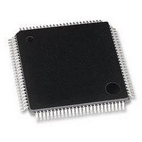
MB95F126JBPFR-GE1 Fujitsu, MB95F126JBPFR-GE1 Datasheet - Page 64

MB95F126JBPFR-GE1
Manufacturer Part Number
MB95F126JBPFR-GE1
Description
MCU, 8-BIT, 8FX, 32K FLASH, QFP100
Manufacturer
Fujitsu
Datasheet
1.MB95F126JBPF-GE1.pdf
(80 pages)
Specifications of MB95F126JBPFR-GE1
Controller Family/series
F2MC-8FX
No. Of I/o's
87
Ram Memory Size
1KB
Cpu Speed
16.25MHz
No. Of Timers
7
No. Of Pwm
RoHS Compliant
Core Size
8bit
Program Memory Size
32KB
Oscillator Type
External Only
- Current page: 64 of 80
- Download datasheet (3Mb)
MB95120MB Series
64
(2) Notes on Using A/D Converter
• About the external impedance of analog input and its sampling time
• About errors
• Analog input equivalent circuit
• The relationship between external impedance and minimum sampling time
A/D converter with sample and hold circuit. If the external impedance is too high to keep sufficient sampling
time, the analog voltage charged to the internal sample and hold capacitor is insufficient, adversely affecting A/
D conversion precision. Therefore to satisfy the A/D conversion precision standard, consider the relationship
between the external impedance and minimum sampling time and either adjust the register value and operating
frequency or decrease the external impedance so that the sampling time is longer than the minimum value. Also,
if the sampling time cannot be sufficient, connect a capacitor of about 0.1 μF to the analog input pin.
As |AV
Note : The values are reference values.
Analog input
(External impedance = 0 kΩ to 100 kΩ)
CC
100
− AV
90
80
70
60
50
40
30
20
10
0
0
SS
| becomes smaller, values of relative errors grow larger.
Minimum sampling time [μs]
2
During sampling : ON
4
AV
CC
6
≥ 4.5 V
AV
8
CC
10
≥ 4.0 V
12
14
R
4.5 V ≤ AVcc ≤ 5.5 V
4.0 V ≤ AVcc < 4.5 V
C
(External impedance = 0 kΩ to 20 kΩ)
Comparator
20
18
16
14
12
10
8
6
4
2
0
0
Minimum sampling time [μs]
2.0 kΩ (Max)
8.2 kΩ (Max)
AV
CC
1
R
≥ 4.5 V
2
AV
16 pF (Max)
16 pF (Max)
CC
≥ 4.0 V
3
C
DS07-12610-5E
4
Related parts for MB95F126JBPFR-GE1
Image
Part Number
Description
Manufacturer
Datasheet
Request
R

Part Number:
Description:
Fujitsu Media Devices Limited [NMOS 1- CHANNEL, 13-BIT AND 3-CHANNEL, 6-BIT D/A CONVERTER]
Manufacturer:
Fujitsu
Datasheet:

Part Number:
Description:
Fujitsu Media Devices Limited [32-bit RISC Microcontroller]
Manufacturer:
Fujitsu
Datasheet:

Part Number:
Description:
Fujitsu Media Devices Limited [MOS 262,144 BIT DYNAMIC RANDOM ACCESS MEMORY]
Manufacturer:
Fujitsu
Datasheet:

Part Number:
Description:
Fujitsu Media Devices Limited [PROGRAMMABLE TIMER]
Manufacturer:
Fujitsu
Datasheet:

Part Number:
Description:
Fujitsu Media Devices Limited [MOS Universal Asynchronous receiver/transmitter(UART)]
Manufacturer:
Fujitsu
Datasheet:

Part Number:
Description:
Fujitsu Media Devices Limited [16M (2M X 8/1M X 16) BIT]
Manufacturer:
Fujitsu
Datasheet:

Part Number:
Description:
KIT, STARTER, MB95200/210/220
Manufacturer:
Fujitsu
Datasheet:

Part Number:
Description:
SWITCHING REGULATOR CONTROLLER
Manufacturer:
Fujitsu
Datasheet:

Part Number:
Description:
QUAD OPERATIONAL AMPLIFIER
Manufacturer:
Fujitsu
Datasheet:

Part Number:
Description:
Switching Regulator Controller (Switchable between push-pull and single-end functions)
Manufacturer:
Fujitsu
Datasheet:

Part Number:
Description:
HIGH-SPEED CMOS SINGLE CHIP 4-BIT MICROCOMPUTER MB88505HHIGH-SPEED CMOS SINGLE CHIP 4-BIT MICROCOMPUTER
Manufacturer:
Fujitsu
Datasheet:

Part Number:
Description:
MOS 1024 BIT NON VOLATILE RANDOM ACCESS MEMORY
Manufacturer:
Fujitsu
Datasheet:

Part Number:
Description:
Schottky TTL 2048-Bit Bipolar Programmable Read-Only Memory
Manufacturer:
Fujitsu
Datasheet:

Part Number:
Description:
QUAD COMPARATOR
Manufacturer:
Fujitsu
Datasheet:


