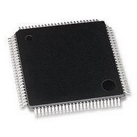
MB95F126JBPFR-GE1 Fujitsu, MB95F126JBPFR-GE1 Datasheet - Page 65

MB95F126JBPFR-GE1
Manufacturer Part Number
MB95F126JBPFR-GE1
Description
MCU, 8-BIT, 8FX, 32K FLASH, QFP100
Manufacturer
Fujitsu
Datasheet
1.MB95F126JBPF-GE1.pdf
(80 pages)
Specifications of MB95F126JBPFR-GE1
Controller Family/series
F2MC-8FX
No. Of I/o's
87
Ram Memory Size
1KB
Cpu Speed
16.25MHz
No. Of Timers
7
No. Of Pwm
RoHS Compliant
Core Size
8bit
Program Memory Size
32KB
Oscillator Type
External Only
- Current page: 65 of 80
- Download datasheet (3Mb)
DS07-12610-5E
(3) Definition of A/D Converter Terms
• Resolution
• Linearity error (unit : LSB)
• Differential linear error (Unit : LSB)
• Total error (unit: LSB)
The level of analog variation that can be distinguished by the A/D converter.
When the number of bits is 10, analog voltage can be divided into 2
The deviation between the value along a straight line connecting the zero transition point
(“00 0000 0000” ← → “00 0000 0001”) of a device and the full-scale transition point
(“11 1111 1111” ← → “11 1111 1110”) compared with the actual conversion values obtained.
Deviation of input voltage, which is required for changing output code by 1 LSB, from an ideal value.
Difference between actual and theoretical values, caused by a zero transition error, full-scale transition error,
linearity error, quantum error, and noise.
1 LSB =
3FF
3FE
3FD
004
003
002
001
N
V
H
H
H
H
H
H
H
NT
AV
: A/D converter digital output value
: A voltage at which digital output transits from (N − 1)
SS
V
OT
0.5 LSB
Ideal I/O characteristics
AVR − AV
1024
Analog input
1 LSB
SS
V
FST
(V)
1.5 LSB
AVR
digital output N
Total error of
3FF
3FE
3FD
004
003
002
001
H
H
H
H
H
H
H
AV
{1 LSB
SS
Actual conversion
characteristic
=
V
H
MB95120MB Series
×
NT
to N
(N
10
− {1 LSB × (N − 1) + 0.5 LSB}
= 1024.
− 1) +
H
Ideal characteristics
Analog input
.
Total error
0.5 LSB}
1 LSB
Actual conversion
characteristic
V
NT
AVR
(Continued)
[LSB]
65
Related parts for MB95F126JBPFR-GE1
Image
Part Number
Description
Manufacturer
Datasheet
Request
R

Part Number:
Description:
Fujitsu Media Devices Limited [NMOS 1- CHANNEL, 13-BIT AND 3-CHANNEL, 6-BIT D/A CONVERTER]
Manufacturer:
Fujitsu
Datasheet:

Part Number:
Description:
Fujitsu Media Devices Limited [32-bit RISC Microcontroller]
Manufacturer:
Fujitsu
Datasheet:

Part Number:
Description:
Fujitsu Media Devices Limited [MOS 262,144 BIT DYNAMIC RANDOM ACCESS MEMORY]
Manufacturer:
Fujitsu
Datasheet:

Part Number:
Description:
Fujitsu Media Devices Limited [PROGRAMMABLE TIMER]
Manufacturer:
Fujitsu
Datasheet:

Part Number:
Description:
Fujitsu Media Devices Limited [MOS Universal Asynchronous receiver/transmitter(UART)]
Manufacturer:
Fujitsu
Datasheet:

Part Number:
Description:
Fujitsu Media Devices Limited [16M (2M X 8/1M X 16) BIT]
Manufacturer:
Fujitsu
Datasheet:

Part Number:
Description:
KIT, STARTER, MB95200/210/220
Manufacturer:
Fujitsu
Datasheet:

Part Number:
Description:
SWITCHING REGULATOR CONTROLLER
Manufacturer:
Fujitsu
Datasheet:

Part Number:
Description:
QUAD OPERATIONAL AMPLIFIER
Manufacturer:
Fujitsu
Datasheet:

Part Number:
Description:
Switching Regulator Controller (Switchable between push-pull and single-end functions)
Manufacturer:
Fujitsu
Datasheet:

Part Number:
Description:
HIGH-SPEED CMOS SINGLE CHIP 4-BIT MICROCOMPUTER MB88505HHIGH-SPEED CMOS SINGLE CHIP 4-BIT MICROCOMPUTER
Manufacturer:
Fujitsu
Datasheet:

Part Number:
Description:
MOS 1024 BIT NON VOLATILE RANDOM ACCESS MEMORY
Manufacturer:
Fujitsu
Datasheet:

Part Number:
Description:
Schottky TTL 2048-Bit Bipolar Programmable Read-Only Memory
Manufacturer:
Fujitsu
Datasheet:

Part Number:
Description:
QUAD COMPARATOR
Manufacturer:
Fujitsu
Datasheet:


