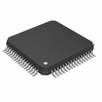
DS26502L+ Maxim Integrated Products, DS26502L+ Datasheet - Page 23

DS26502L+
Manufacturer Part Number
DS26502L+
Description
IC T1/E1/J1 64KCC ELEMENT 64LQFP
Manufacturer
Maxim Integrated Products
Type
BITS Elementr
Datasheet
1.DS26502LN.pdf
(125 pages)
Specifications of DS26502L+
Voltage - Supply
3.135 V ~ 3.465 V
Operating Temperature
0°C ~ 70°C
Mounting Type
Surface Mount
Package / Case
64-LQFP
Lead Free Status / RoHS Status
Lead free / RoHS Compliant
Frequency-max
-
Output
-
Input
-
- Current page: 23 of 125
- Download datasheet (4Mb)
5. PINOUT
Table 5-1. LQFP Pinout
7, 24,
8, 22,
PIN
58
56
10
11
12
13
14
15
16
17
1
2
3
4
5
6
9
TYPE
I/O
I/O
I/O
I/O
I/O
I/O
I
I
I
I
I
I
I
I
I
I
I
ALE (AS)/A7
PARALLEL
DVDD
PORT
TCLK
DVSS
AD2
AD3
AD4
AD5
AD6
AD7
A0
A1
A2
A3
A4
A5
A6
SERIAL
MODE
DVDD
PORT
CPHA
SCLK
DVSS
CPOL
TCLK
—
—
—
—
—
—
—
—
—
—
—
HARDWARE
RMODE0
RMODE1
TMODE0
23 of 125
DVDD
DVSS
TCLK
MPS0
MPS1
RITD
TITD
E1TS
TAIS
RSM
TSM
L0
L1
L2
Parallel Port Mode: Address/Data Bus Bit 2
Serial Port Mode: Serial Clock
Hardware Mode: RS_8K Mode Select
Parallel Port Mode: Address/Data Bus Bit 3
Serial Port Mode: Unused, should be connected to V
Hardware Mode: TS_8K_4 Mode Select
Parallel Port Mode: Address/Data Bus Bit 4
Serial Port Mode: Unused, should be connected to V
Hardware Mode: Receive Mode Select 0
Parallel Port Mode: Address/Data Bus Bit 5
Serial Port Mode: Unused, should be connected to V
Hardware Mode: Receive Mode Select 1
Parallel Port Mode: Address/Data Bus Bit 6
Serial Port Mode: Unused, should be connected to V
Hardware Mode: Transmit Internal Termination Disable
Parallel Port Mode: Address/Data Bus Bit 7
Serial Port Mode: Unused, should be connected to V
Hardware Mode: Receive Internal Termination Disable
Digital Positive Supply
Digital Signal Ground
Parallel Port Mode: Address Bus Bit 0
Serial Port Mode: Unused, should be connected to V
Hardware Mode: E1 Internal Termination Select
Parallel Port Mode: Address Bus Bit 1
Serial Port Mode: Unused, should be connected to V
Hardware Mode: Transmit AIS
Parallel Port Mode: Address Bus Bit 2
Serial Port Mode: Unused, should be connected to V
Hardware Mode: Line Build-Out Select 0
Parallel Port Mode: Address Bus Bit 3
Serial Port Mode: Unused, should be connected to V
Hardware Mode: Line Build-Out Select 1
Parallel Port Mode: Address Bus Bit 4
Serial Port Mode: Serial Port Clock Phase Select
Hardware Mode: Line Build-Out Select 2
Parallel Port Mode: Address Bus Bit 5
Serial Port Mode: Serial Port Clock Polarity Select
Hardware Mode: Transmit Mode Select 0
Parallel Port Mode: Address Bus Bit 6
Serial Port Mode: Unused, should be connected to V
Hardware Mode: MCLK Pre-Scaler Select 0
Parallel Port Mode: Address Latch Enable/Address Bus
Bit 7
Serial Port Mode: Unused, should be connected to V
Hardware Mode: MCLK Pre-Scaler Select 1
Transmit Clock Input
DS26502 T1/E1/J1/64KCC BITS Element
FUNCTION
SS
SS
SS
SS
SS
SS
SS
SS
SS
SS
SS
.
.
.
.
.
.
.
.
.
.
.
Related parts for DS26502L+
Image
Part Number
Description
Manufacturer
Datasheet
Request
R

Part Number:
Description:
MAX7528KCWPMaxim Integrated Products [CMOS Dual 8-Bit Buffered Multiplying DACs]
Manufacturer:
Maxim Integrated Products
Datasheet:

Part Number:
Description:
Single +5V, fully integrated, 1.25Gbps laser diode driver.
Manufacturer:
Maxim Integrated Products
Datasheet:

Part Number:
Description:
Single +5V, fully integrated, 155Mbps laser diode driver.
Manufacturer:
Maxim Integrated Products
Datasheet:

Part Number:
Description:
VRD11/VRD10, K8 Rev F 2/3/4-Phase PWM Controllers with Integrated Dual MOSFET Drivers
Manufacturer:
Maxim Integrated Products
Datasheet:

Part Number:
Description:
Highly Integrated Level 2 SMBus Battery Chargers
Manufacturer:
Maxim Integrated Products
Datasheet:

Part Number:
Description:
Current Monitor and Accumulator with Integrated Sense Resistor; ; Temperature Range: -40°C to +85°C
Manufacturer:
Maxim Integrated Products

Part Number:
Description:
TSSOP 14/A°/RS-485 Transceivers with Integrated 100O/120O Termination Resis
Manufacturer:
Maxim Integrated Products

Part Number:
Description:
TSSOP 14/A°/RS-485 Transceivers with Integrated 100O/120O Termination Resis
Manufacturer:
Maxim Integrated Products

Part Number:
Description:
QFN 16/A°/AC-DC and DC-DC Peak-Current-Mode Converters with Integrated Step
Manufacturer:
Maxim Integrated Products

Part Number:
Description:
TDFN/A/65V, 1A, 600KHZ, SYNCHRONOUS STEP-DOWN REGULATOR WITH INTEGRATED SWI
Manufacturer:
Maxim Integrated Products

Part Number:
Description:
Integrated Temperature Controller f
Manufacturer:
Maxim Integrated Products

Part Number:
Description:
SOT23-6/I°/45MHz to 650MHz, Integrated IF VCOs with Differential Output
Manufacturer:
Maxim Integrated Products

Part Number:
Description:
SOT23-6/I°/45MHz to 650MHz, Integrated IF VCOs with Differential Output
Manufacturer:
Maxim Integrated Products

Part Number:
Description:
EVALUATION KIT/2.4GHZ TO 2.5GHZ 802.11G/B RF TRANSCEIVER WITH INTEGRATED PA
Manufacturer:
Maxim Integrated Products

Part Number:
Description:
QFN/E/DUAL PCIE/SATA HIGH SPEED SWITCH WITH INTEGRATED BIAS RESISTOR
Manufacturer:
Maxim Integrated Products
Datasheet:


