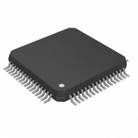
DS26502L+ Maxim Integrated Products, DS26502L+ Datasheet - Page 36

DS26502L+
Manufacturer Part Number
DS26502L+
Description
IC T1/E1/J1 64KCC ELEMENT 64LQFP
Manufacturer
Maxim Integrated Products
Type
BITS Elementr
Datasheet
1.DS26502LN.pdf
(125 pages)
Specifications of DS26502L+
Voltage - Supply
3.135 V ~ 3.465 V
Operating Temperature
0°C ~ 70°C
Mounting Type
Surface Mount
Package / Case
64-LQFP
Lead Free Status / RoHS Status
Lead free / RoHS Compliant
Frequency-max
-
Output
-
Input
-
- Current page: 36 of 125
- Download datasheet (4Mb)
Note 1:
Note 2:
Bits 4 to 7: Transmit Mode Configuration (TMODE[3:0]). Used to select the operating mode of the transmit path for the
DS26502.
TMODE3
0
0
0
0
0
0
0
0
0
0
1
1
1
1
1
1
The DS26502 does not have an internal source for CAS signaling and multiframe alignment generation. CAS signaling, and the
In addition to setting the TMODE bits to 6312kHz Synchronization Interface mode, the Transmit PLL must also be configured to
multiframe alignment word, must be embedded in the transmit data (in the TS16 position) present on the TSER pin and frame
aligned to sync signal on the TS_8K_4 pin.
transmit a 6312kHz signal through the Transmit PLL Control Register (TPCR.6 and TPCR.7)
TMODE2
0
0
0
0
1
1
1
1
1
1
0
0
0
0
1
1
TMODE1
0
0
1
1
0
0
0
1
1
1
0
0
1
1
0
0
TMODE0
0
1
0
1
0
0
1
0
0
1
0
1
0
1
0
1
T1 ESF (Note: In this mode the TFSE (T1TCR2.6) bit should be
36 of 125
64kHz + 8kHz + 400Hz Synchronization Interface
E1 G.703 2048 kHz Synchronization Interface
6312kHz Synchronization Interface (Note 2)
64kHz + 8kHz Synchronization Interface
Transmit Path Operating Mode
E1 CRC4 + CAS (Note 1)
E1 FAS + CAS (Note 1)
E1 CRC4
Reserved
Reserved
Reserved
Reserved
set = 0.)
E1 FAS
J1 ESF
T1 D4
J1 D4
Related parts for DS26502L+
Image
Part Number
Description
Manufacturer
Datasheet
Request
R

Part Number:
Description:
MAX7528KCWPMaxim Integrated Products [CMOS Dual 8-Bit Buffered Multiplying DACs]
Manufacturer:
Maxim Integrated Products
Datasheet:

Part Number:
Description:
Single +5V, fully integrated, 1.25Gbps laser diode driver.
Manufacturer:
Maxim Integrated Products
Datasheet:

Part Number:
Description:
Single +5V, fully integrated, 155Mbps laser diode driver.
Manufacturer:
Maxim Integrated Products
Datasheet:

Part Number:
Description:
VRD11/VRD10, K8 Rev F 2/3/4-Phase PWM Controllers with Integrated Dual MOSFET Drivers
Manufacturer:
Maxim Integrated Products
Datasheet:

Part Number:
Description:
Highly Integrated Level 2 SMBus Battery Chargers
Manufacturer:
Maxim Integrated Products
Datasheet:

Part Number:
Description:
Current Monitor and Accumulator with Integrated Sense Resistor; ; Temperature Range: -40°C to +85°C
Manufacturer:
Maxim Integrated Products

Part Number:
Description:
TSSOP 14/A°/RS-485 Transceivers with Integrated 100O/120O Termination Resis
Manufacturer:
Maxim Integrated Products

Part Number:
Description:
TSSOP 14/A°/RS-485 Transceivers with Integrated 100O/120O Termination Resis
Manufacturer:
Maxim Integrated Products

Part Number:
Description:
QFN 16/A°/AC-DC and DC-DC Peak-Current-Mode Converters with Integrated Step
Manufacturer:
Maxim Integrated Products

Part Number:
Description:
TDFN/A/65V, 1A, 600KHZ, SYNCHRONOUS STEP-DOWN REGULATOR WITH INTEGRATED SWI
Manufacturer:
Maxim Integrated Products

Part Number:
Description:
Integrated Temperature Controller f
Manufacturer:
Maxim Integrated Products

Part Number:
Description:
SOT23-6/I°/45MHz to 650MHz, Integrated IF VCOs with Differential Output
Manufacturer:
Maxim Integrated Products

Part Number:
Description:
SOT23-6/I°/45MHz to 650MHz, Integrated IF VCOs with Differential Output
Manufacturer:
Maxim Integrated Products

Part Number:
Description:
EVALUATION KIT/2.4GHZ TO 2.5GHZ 802.11G/B RF TRANSCEIVER WITH INTEGRATED PA
Manufacturer:
Maxim Integrated Products

Part Number:
Description:
QFN/E/DUAL PCIE/SATA HIGH SPEED SWITCH WITH INTEGRATED BIAS RESISTOR
Manufacturer:
Maxim Integrated Products
Datasheet:


