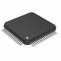
DS26502L+ Maxim Integrated Products, DS26502L+ Datasheet - Page 50

DS26502L+
Manufacturer Part Number
DS26502L+
Description
IC T1/E1/J1 64KCC ELEMENT 64LQFP
Manufacturer
Maxim Integrated Products
Type
BITS Elementr
Datasheet
1.DS26502LN.pdf
(125 pages)
Specifications of DS26502L+
Voltage - Supply
3.135 V ~ 3.465 V
Operating Temperature
0°C ~ 70°C
Mounting Type
Surface Mount
Package / Case
64-LQFP
Lead Free Status / RoHS Status
Lead free / RoHS Compliant
Frequency-max
-
Output
-
Input
-
- Current page: 50 of 125
- Download datasheet (4Mb)
Register Name:
Register Description:
Register Address:
Bit #
Name
Default
HW
Mode
Bit 0: Receive Loss of Frame Condition (RLOF). Set when the DS26502 is not synchronized to the received data stream.
Bit 1: Receive Loss Of Signal Condition (RLOS). Set when 255 (or 2048 if E1RCR.6 = 1) E1 mode or 192 T1 mode
consecutive zeros have been detected. In 6312kHz Synchronization Interface Mode, this bit will be set when the signal
received is out of range as defined by the G.703 Appendix II specification.
Bit 2: Receive Alarm Indication Signal (T1= Blue Alarm, E1= AIS) Condition (RAIS). Set when an unframed all-ones
code is received.
Bit 3: Receive Yellow Alarm Condition (RYEL). (T1 only) Set when a yellow alarm is received.
Bit 4: Receive Loss of Frame Clear Event (RLOFC). Set when the framer achieves synchronization; will remain set until
read.
Bit 5: Receive Loss Of Signal Clear Event (RLOSC). Set when loss of signal condition is no longer detected.
Bit 6: Receive Alarm Indication Signal Clear Event (RAISC). Set when the unframed all-ones condition is no longer
detected.
Bit 7: Receive Yellow Alarm Clear Event (RYELC). (T1 only) Set when the yellow alarm condition is no longer detected
RYELC
X
7
0
RAISC
SR2
Status Register 2
16h
X
6
0
RLOSC
X
5
0
RLOFC
X
4
0
50 of 125
RYEL
X
3
0
PIN 29
RAIS
RAIS
2
0
PIN 32
RLOS
RLOS
1
0
PIN 30
RLOF
LOF
0
0
.
Related parts for DS26502L+
Image
Part Number
Description
Manufacturer
Datasheet
Request
R

Part Number:
Description:
MAX7528KCWPMaxim Integrated Products [CMOS Dual 8-Bit Buffered Multiplying DACs]
Manufacturer:
Maxim Integrated Products
Datasheet:

Part Number:
Description:
Single +5V, fully integrated, 1.25Gbps laser diode driver.
Manufacturer:
Maxim Integrated Products
Datasheet:

Part Number:
Description:
Single +5V, fully integrated, 155Mbps laser diode driver.
Manufacturer:
Maxim Integrated Products
Datasheet:

Part Number:
Description:
VRD11/VRD10, K8 Rev F 2/3/4-Phase PWM Controllers with Integrated Dual MOSFET Drivers
Manufacturer:
Maxim Integrated Products
Datasheet:

Part Number:
Description:
Highly Integrated Level 2 SMBus Battery Chargers
Manufacturer:
Maxim Integrated Products
Datasheet:

Part Number:
Description:
Current Monitor and Accumulator with Integrated Sense Resistor; ; Temperature Range: -40°C to +85°C
Manufacturer:
Maxim Integrated Products

Part Number:
Description:
TSSOP 14/A°/RS-485 Transceivers with Integrated 100O/120O Termination Resis
Manufacturer:
Maxim Integrated Products

Part Number:
Description:
TSSOP 14/A°/RS-485 Transceivers with Integrated 100O/120O Termination Resis
Manufacturer:
Maxim Integrated Products

Part Number:
Description:
QFN 16/A°/AC-DC and DC-DC Peak-Current-Mode Converters with Integrated Step
Manufacturer:
Maxim Integrated Products

Part Number:
Description:
TDFN/A/65V, 1A, 600KHZ, SYNCHRONOUS STEP-DOWN REGULATOR WITH INTEGRATED SWI
Manufacturer:
Maxim Integrated Products

Part Number:
Description:
Integrated Temperature Controller f
Manufacturer:
Maxim Integrated Products

Part Number:
Description:
SOT23-6/I°/45MHz to 650MHz, Integrated IF VCOs with Differential Output
Manufacturer:
Maxim Integrated Products

Part Number:
Description:
SOT23-6/I°/45MHz to 650MHz, Integrated IF VCOs with Differential Output
Manufacturer:
Maxim Integrated Products

Part Number:
Description:
EVALUATION KIT/2.4GHZ TO 2.5GHZ 802.11G/B RF TRANSCEIVER WITH INTEGRATED PA
Manufacturer:
Maxim Integrated Products

Part Number:
Description:
QFN/E/DUAL PCIE/SATA HIGH SPEED SWITCH WITH INTEGRATED BIAS RESISTOR
Manufacturer:
Maxim Integrated Products
Datasheet:


