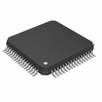
DS26502L+ Maxim Integrated Products, DS26502L+ Datasheet - Page 74

DS26502L+
Manufacturer Part Number
DS26502L+
Description
IC T1/E1/J1 64KCC ELEMENT 64LQFP
Manufacturer
Maxim Integrated Products
Type
BITS Elementr
Datasheet
1.DS26502LN.pdf
(125 pages)
Specifications of DS26502L+
Voltage - Supply
3.135 V ~ 3.465 V
Operating Temperature
0°C ~ 70°C
Mounting Type
Surface Mount
Package / Case
64-LQFP
Lead Free Status / RoHS Status
Lead free / RoHS Compliant
Frequency-max
-
Output
-
Input
-
- Current page: 74 of 125
- Download datasheet (4Mb)
12.2 Alternate Sa/Si Bit Access Based on Double-Frame
On the receive side, the RAF and RNAF registers will always report the data as it received in the Sa and
Si bit locations. The RAF and RNAF registers are updated on align frame boundaries. The setting of the
receive align frame bit in status register 4 (SR4.0) will indicate that the contents of the RAF and RNAF
have been updated. The host can use the SR4.0 bit to know when to read the RAF and RNAF registers.
The host has 250µs to retrieve the data before it is lost.
On the transmit side, data is sampled from the TAF and TNAF registers with the setting of the transmit
align frame bit in status register 4 (SR4.3). The host can use the SR4.3 bit to know when to update the
TAF and TNAF registers. It has 250µs to update the data or else the old data will be retransmitted. If the
TAF an TNAF registers are only being used to source the align frame and non-align frame-sync
patterns, then the host need only write once to these registers. Data for the Si bit can come from the Si
bits of the RAF and TNAF registers, the TSiAF and TSiNAF registers, or passed through from the TSER
pin.
Register Name:
Register Description:
Register Address:
Bit #
Name
Default
HW
Mode
Bit 0: Frame Alignment Signal Bit 0 (FAS0). In normal operation this bit will be = 1.
Bit 1: Frame Alignment Signal Bit 1 (FAS1). In normal operation this bit will be = 1.
Bit 2: Frame Alignment Signal Bit 2 (FAS2). In normal operation this bit will be = 0.
Bit 3: Frame Alignment Signal Bit 3 (FAS3). In normal operation this bit will be = 1.
Bit 4: Frame Alignment Signal Bit 4 (FAS4). In normal operation this bit will be = 1.
Bit 5: Frame Alignment Signal Bit 5 (FAS5). In normal operation this bit will be = 0.
Bit 6: Frame Alignment Signal Bit 6 (FAS6). In normal operation this bit will be = 0.
Bit 7: International Bit (Si)
Si
X
7
0
FAS6
RAF
Receive Align Frame Register
56h
X
6
0
FAS5
X
5
0
FAS4
X
4
0
74 of 125
FAS3
X
3
0
FAS2
X
2
0
FAS1
X
1
0
FAS0
X
0
0
Related parts for DS26502L+
Image
Part Number
Description
Manufacturer
Datasheet
Request
R

Part Number:
Description:
MAX7528KCWPMaxim Integrated Products [CMOS Dual 8-Bit Buffered Multiplying DACs]
Manufacturer:
Maxim Integrated Products
Datasheet:

Part Number:
Description:
Single +5V, fully integrated, 1.25Gbps laser diode driver.
Manufacturer:
Maxim Integrated Products
Datasheet:

Part Number:
Description:
Single +5V, fully integrated, 155Mbps laser diode driver.
Manufacturer:
Maxim Integrated Products
Datasheet:

Part Number:
Description:
VRD11/VRD10, K8 Rev F 2/3/4-Phase PWM Controllers with Integrated Dual MOSFET Drivers
Manufacturer:
Maxim Integrated Products
Datasheet:

Part Number:
Description:
Highly Integrated Level 2 SMBus Battery Chargers
Manufacturer:
Maxim Integrated Products
Datasheet:

Part Number:
Description:
Current Monitor and Accumulator with Integrated Sense Resistor; ; Temperature Range: -40°C to +85°C
Manufacturer:
Maxim Integrated Products

Part Number:
Description:
TSSOP 14/A°/RS-485 Transceivers with Integrated 100O/120O Termination Resis
Manufacturer:
Maxim Integrated Products

Part Number:
Description:
TSSOP 14/A°/RS-485 Transceivers with Integrated 100O/120O Termination Resis
Manufacturer:
Maxim Integrated Products

Part Number:
Description:
QFN 16/A°/AC-DC and DC-DC Peak-Current-Mode Converters with Integrated Step
Manufacturer:
Maxim Integrated Products

Part Number:
Description:
TDFN/A/65V, 1A, 600KHZ, SYNCHRONOUS STEP-DOWN REGULATOR WITH INTEGRATED SWI
Manufacturer:
Maxim Integrated Products

Part Number:
Description:
Integrated Temperature Controller f
Manufacturer:
Maxim Integrated Products

Part Number:
Description:
SOT23-6/I°/45MHz to 650MHz, Integrated IF VCOs with Differential Output
Manufacturer:
Maxim Integrated Products

Part Number:
Description:
SOT23-6/I°/45MHz to 650MHz, Integrated IF VCOs with Differential Output
Manufacturer:
Maxim Integrated Products

Part Number:
Description:
EVALUATION KIT/2.4GHZ TO 2.5GHZ 802.11G/B RF TRANSCEIVER WITH INTEGRATED PA
Manufacturer:
Maxim Integrated Products

Part Number:
Description:
QFN/E/DUAL PCIE/SATA HIGH SPEED SWITCH WITH INTEGRATED BIAS RESISTOR
Manufacturer:
Maxim Integrated Products
Datasheet:


