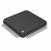
DS26502L+ Maxim Integrated Products, DS26502L+ Datasheet - Page 91

DS26502L+
Manufacturer Part Number
DS26502L+
Description
IC T1/E1/J1 64KCC ELEMENT 64LQFP
Manufacturer
Maxim Integrated Products
Type
BITS Elementr
Datasheet
1.DS26502LN.pdf
(125 pages)
Specifications of DS26502L+
Voltage - Supply
3.135 V ~ 3.465 V
Operating Temperature
0°C ~ 70°C
Mounting Type
Surface Mount
Package / Case
64-LQFP
Lead Free Status / RoHS Status
Lead free / RoHS Compliant
Frequency-max
-
Output
-
Input
-
- Current page: 91 of 125
- Download datasheet (4Mb)
Figure 13-5. Software-Selected Termination, Longitudinal Protection
Table 13-2. Component List (Software-Selected Termination, Longitudinal
Protection)
RING
RING
TIP
TIP
Note 1:
Note 2:
Note 3:
Note 4:
Note 5:
RX
TX
TX
RX
S3, S4, S5, S6
T1 and T2
T3 and T4
S1 and S2
S7 and S8
F1 to F4
NAME
F2
F3
F4
F1
T3 and T4 are optional. For more information, contact the Telecom Support Group at
www.maxim-ic.com/support.
A list of alternate transformer part numbers and manufacturers is available at
www.maxim-ic.com/support.
The layout from the transformers to the network interface is critical. Traces should be at least 25
mils wide and separated from other circuit lines by at least 150 mils. The area under this portion
of the circuit should not contain power planes.
Some T1 (never in E1) applications source or sink power from the network-side center taps of
the Rx/Tx transformers.
The ground trace connected to the S2/S3 pair and the S4/S5 pair should be at least 50 mils wide
to conduct the extra current from a longitudinal power-cross event.
S8
S7
1.25A slow blow fuse
Transformer 1:1CT and 1:136CT (5.0V, SMT) (Note 2)
Transformer 1:1CT and 1:2CT (3.3V, SMT) (Note 2)
25V (max) transient suppressor (Note 1)
180V (max) transient suppressor (Note 1)
40V (max) transient suppressor
Dual common-mode choke (SMT)
S3
S4
S5
S6
T3
T4
DESCRIPTION
1:1
T1
2:1
T2
91 of 125
60
S1
S2
10uF
0.1 uF
60
RRING
TTIP
TRING
RTIP
DS26502
DVDD
RVDD
DVSS
TVDD
RVSS
TVSS
0.1 uF
0.1 uF
0.01 uF
3.3 V
3.3 V
DS26502
0.1 uF
68 uF
Related parts for DS26502L+
Image
Part Number
Description
Manufacturer
Datasheet
Request
R

Part Number:
Description:
MAX7528KCWPMaxim Integrated Products [CMOS Dual 8-Bit Buffered Multiplying DACs]
Manufacturer:
Maxim Integrated Products
Datasheet:

Part Number:
Description:
Single +5V, fully integrated, 1.25Gbps laser diode driver.
Manufacturer:
Maxim Integrated Products
Datasheet:

Part Number:
Description:
Single +5V, fully integrated, 155Mbps laser diode driver.
Manufacturer:
Maxim Integrated Products
Datasheet:

Part Number:
Description:
VRD11/VRD10, K8 Rev F 2/3/4-Phase PWM Controllers with Integrated Dual MOSFET Drivers
Manufacturer:
Maxim Integrated Products
Datasheet:

Part Number:
Description:
Highly Integrated Level 2 SMBus Battery Chargers
Manufacturer:
Maxim Integrated Products
Datasheet:

Part Number:
Description:
Current Monitor and Accumulator with Integrated Sense Resistor; ; Temperature Range: -40°C to +85°C
Manufacturer:
Maxim Integrated Products

Part Number:
Description:
TSSOP 14/A°/RS-485 Transceivers with Integrated 100O/120O Termination Resis
Manufacturer:
Maxim Integrated Products

Part Number:
Description:
TSSOP 14/A°/RS-485 Transceivers with Integrated 100O/120O Termination Resis
Manufacturer:
Maxim Integrated Products

Part Number:
Description:
QFN 16/A°/AC-DC and DC-DC Peak-Current-Mode Converters with Integrated Step
Manufacturer:
Maxim Integrated Products

Part Number:
Description:
TDFN/A/65V, 1A, 600KHZ, SYNCHRONOUS STEP-DOWN REGULATOR WITH INTEGRATED SWI
Manufacturer:
Maxim Integrated Products

Part Number:
Description:
Integrated Temperature Controller f
Manufacturer:
Maxim Integrated Products

Part Number:
Description:
SOT23-6/I°/45MHz to 650MHz, Integrated IF VCOs with Differential Output
Manufacturer:
Maxim Integrated Products

Part Number:
Description:
SOT23-6/I°/45MHz to 650MHz, Integrated IF VCOs with Differential Output
Manufacturer:
Maxim Integrated Products

Part Number:
Description:
EVALUATION KIT/2.4GHZ TO 2.5GHZ 802.11G/B RF TRANSCEIVER WITH INTEGRATED PA
Manufacturer:
Maxim Integrated Products

Part Number:
Description:
QFN/E/DUAL PCIE/SATA HIGH SPEED SWITCH WITH INTEGRATED BIAS RESISTOR
Manufacturer:
Maxim Integrated Products
Datasheet:


