C8051F360DK Silicon Laboratories Inc, C8051F360DK Datasheet - Page 104
C8051F360DK
Manufacturer Part Number
C8051F360DK
Description
KIT DEV FOR C8051F360 FAMILY
Manufacturer
Silicon Laboratories Inc
Type
MCUr
Specifications of C8051F360DK
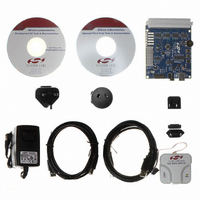
Contents
Evaluation Board, Power Supply, USB Cables, Adapter and Documentation
Processor To Be Evaluated
C8051F36x
Interface Type
USB
Lead Free Status / RoHS Status
Lead free / RoHS Compliant
For Use With/related Products
C8051F360, F361, F362, F363, F364, F365, F366, F367, F368, F369
Lead Free Status / Rohs Status
Lead free / RoHS Compliant
Other names
336-1410


C8051F360/1/2/3/4/5/6/7/8/9
9.5.
The CIP-51 core has two software programmable power management modes: Idle and Stop. Idle mode
halts the CPU while leaving the external peripherals and internal clocks active. In Stop mode, the CPU is
halted, all interrupts and timers (except the Missing Clock Detector) are inactive, and the system clock is
stopped. Since clocks are running in Idle mode, power consumption is dependent upon the system clock
frequency and the number of peripherals left in active mode before entering Idle. Stop mode consumes the
least power. SFR Definition 9.11 describes the Power Control Register (PCON) used to control the CIP-
51's power management modes.
Although the CIP-51 has Idle and Stop modes built in (as with any standard 8051 architecture), power
management of the entire MCU is better accomplished by enabling/disabling individual peripherals as
needed. Each analog peripheral can be disabled when not in use and put into low power mode. Digital
peripherals, such as timers or serial buses, draw little power whenever they are not in use. Turning off the
Flash memory saves power, similar to entering Idle mode. Turning off the oscillator saves even more
power, but requires a reset to restart the MCU.
The C8051F36x devices feature an additional low-power SUSPEND mode, which stops the internal oscil-
lator until an awakening event occurs. See Section “16.1.1. Internal Oscillator Suspend Mode” on
page 170 for more information.
104
Bits 7–0: ACC: Accumulator.
Bits 7–0: B: B Register.
SFR Page:
SFR Address:
SFR Page:
SFR Address:
ACC.7
R/W
R/W
B.7
Bit7
Bit7
Power Management Modes
This register is the accumulator for arithmetic operations.
This register serves as a second accumulator for certain arithmetic operations.
all pages
0xE0
all pages
0xF0
ACC.6
R/W
R/W
B.6
Bit6
Bit6
ACC.5
SFR Definition 9.9. ACC: Accumulator
R/W
R/W
B.5
Bit5
Bit5
(bit addressable)
(bit addressable)
SFR Definition 9.10. B: B Register
ACC.4
R/W
R/W
B.4
Bit4
Bit4
Rev. 1.0
ACC.3
R/W
R/W
B.3
Bit3
Bit3
ACC.2
R/W
R/W
Bit2
B.2
Bit2
ACC.1
R/W
R/W
B.1
Bit1
Bit1
ACC.0
R/W
R/W
B.0
Bit0
Bit0
00000000
00000000
Reset Value
Reset Value
Related parts for C8051F360DK
Image
Part Number
Description
Manufacturer
Datasheet
Request
R

Part Number:
Description:
SMD/C°/SINGLE-ENDED OUTPUT SILICON OSCILLATOR
Manufacturer:
Silicon Laboratories Inc
Part Number:
Description:
Manufacturer:
Silicon Laboratories Inc
Datasheet:
Part Number:
Description:
N/A N/A/SI4010 AES KEYFOB DEMO WITH LCD RX
Manufacturer:
Silicon Laboratories Inc
Datasheet:
Part Number:
Description:
N/A N/A/SI4010 SIMPLIFIED KEY FOB DEMO WITH LED RX
Manufacturer:
Silicon Laboratories Inc
Datasheet:
Part Number:
Description:
N/A/-40 TO 85 OC/EZLINK MODULE; F930/4432 HIGH BAND (REV E/B1)
Manufacturer:
Silicon Laboratories Inc
Part Number:
Description:
EZLink Module; F930/4432 Low Band (rev e/B1)
Manufacturer:
Silicon Laboratories Inc
Part Number:
Description:
I°/4460 10 DBM RADIO TEST CARD 434 MHZ
Manufacturer:
Silicon Laboratories Inc
Part Number:
Description:
I°/4461 14 DBM RADIO TEST CARD 868 MHZ
Manufacturer:
Silicon Laboratories Inc
Part Number:
Description:
I°/4463 20 DBM RFSWITCH RADIO TEST CARD 460 MHZ
Manufacturer:
Silicon Laboratories Inc
Part Number:
Description:
I°/4463 20 DBM RADIO TEST CARD 868 MHZ
Manufacturer:
Silicon Laboratories Inc
Part Number:
Description:
I°/4463 27 DBM RADIO TEST CARD 868 MHZ
Manufacturer:
Silicon Laboratories Inc
Part Number:
Description:
I°/4463 SKYWORKS 30 DBM RADIO TEST CARD 915 MHZ
Manufacturer:
Silicon Laboratories Inc
Part Number:
Description:
N/A N/A/-40 TO 85 OC/4463 RFMD 30 DBM RADIO TEST CARD 915 MHZ
Manufacturer:
Silicon Laboratories Inc
Part Number:
Description:
I°/4463 20 DBM RADIO TEST CARD 169 MHZ
Manufacturer:
Silicon Laboratories Inc