DEMO9S08JM16 Freescale Semiconductor, DEMO9S08JM16 Datasheet - Page 14
DEMO9S08JM16
Manufacturer Part Number
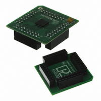
DEMO9S08JM16
Description
BOARD DEMO FOR JM16 FAMI
Manufacturer
Freescale Semiconductor
Type
MCUr
Datasheets
1.DEMO9S08JM16.pdf
(47 pages)
2.DEMO9S08JM16.pdf
(5 pages)
3.DEMO9S08JM16.pdf
(4 pages)
4.DEMO9S08JM16.pdf
(386 pages)
Specifications of DEMO9S08JM16
Contents
Board with Daughter card, Cable, Documentation, Mini-AB USB Kit
Processor To Be Evaluated
MC9S08JM16
Data Bus Width
8 bit
Interface Type
USB
Silicon Manufacturer
Freescale
Core Architecture
HCS08
Core Sub-architecture
HCS08
Silicon Core Number
MC9S08
Silicon Family Name
Flexis - S08JM
Rohs Compliant
Yes
For Use With/related Products
MC9S08JM16
Lead Free Status / RoHS Status
Lead free / RoHS Compliant


11.5 Resets ............................................................................................................................................173
11.6 Interrupts .......................................................................................................................................173
11.7 Initialization/Application Information ..........................................................................................175
12.1 Introduction ...................................................................................................................................177
12.2 External Signal Description ..........................................................................................................181
12.3 Register Definition ........................................................................................................................182
12.4 Functional Description ..................................................................................................................188
12.5 Initialization / Application Information ........................................................................................194
13.1 Introduction ...................................................................................................................................209
13.2 External Signal Description ..........................................................................................................212
13.3 Register Definition ........................................................................................................................212
13.4 Functional Description ..................................................................................................................214
14
11.4.3 General Call Address ......................................................................................................173
11.6.1 Byte Transfer Interrupt ....................................................................................................173
11.6.2 Address Detect Interrupt .................................................................................................174
11.6.3 Arbitration Lost Interrupt ................................................................................................174
12.1.1 Features ...........................................................................................................................179
12.1.2 Modes of Operation ........................................................................................................181
12.3.1 MCG Control Register 1 (MCGC1) ...............................................................................182
12.3.2 MCG Control Register 2 (MCGC2) ...............................................................................183
12.3.3 MCG Trim Register (MCGTRM) ...................................................................................184
12.3.4 MCG Status and Control Register (MCGSC) .................................................................185
12.3.5 MCG Control Register 3 (MCGC3) ...............................................................................186
12.4.1 Operational Modes ..........................................................................................................188
12.4.2 Mode Switching ..............................................................................................................192
12.4.3 Bus Frequency Divider ...................................................................................................192
12.4.4 Low Power Bit Usage .....................................................................................................193
12.4.5 Internal Reference Clock ................................................................................................193
12.4.6 External Reference Clock ...............................................................................................193
12.4.7 Fixed Frequency Clock ...................................................................................................193
12.5.1 MCG Module Initialization Sequence ............................................................................194
12.5.2 MCG Mode Switching ....................................................................................................195
12.5.3 Calibrating the Internal Reference Clock (IRC) .............................................................206
13.1.1 Features ...........................................................................................................................211
13.1.2 Modes of Operation ........................................................................................................211
13.1.3 Block Diagram ................................................................................................................212
13.3.1 RTC Status and Control Register (RTCSC) ....................................................................213
13.3.2 RTC Counter Register (RTCCNT) ..................................................................................214
13.3.3 RTC Modulo Register (RTCMOD) ................................................................................214
Multi-Purpose Clock Generator (S08MCGV1)
Real-Time Counter (S08RTCV1)
MC9S08JM16 Series Data Sheet, Rev. 2
Chapter 12
Chapter 13
Freescale Semiconductor
Related parts for DEMO9S08JM16
Image
Part Number
Description
Manufacturer
Datasheet
Request
R

Part Number:
Description:
Manufacturer:
Freescale Semiconductor, Inc
Datasheet:
Part Number:
Description:
Manufacturer:
Freescale Semiconductor, Inc
Datasheet:
Part Number:
Description:
Manufacturer:
Freescale Semiconductor, Inc
Datasheet:
Part Number:
Description:
Manufacturer:
Freescale Semiconductor, Inc
Datasheet:
Part Number:
Description:
Manufacturer:
Freescale Semiconductor, Inc
Datasheet:
Part Number:
Description:
Manufacturer:
Freescale Semiconductor, Inc
Datasheet:
Part Number:
Description:
Manufacturer:
Freescale Semiconductor, Inc
Datasheet:
Part Number:
Description:
Manufacturer:
Freescale Semiconductor, Inc
Datasheet:
Part Number:
Description:
Manufacturer:
Freescale Semiconductor, Inc
Datasheet:
Part Number:
Description:
Manufacturer:
Freescale Semiconductor, Inc
Datasheet:
Part Number:
Description:
Manufacturer:
Freescale Semiconductor, Inc
Datasheet:
Part Number:
Description:
Manufacturer:
Freescale Semiconductor, Inc
Datasheet:
Part Number:
Description:
Manufacturer:
Freescale Semiconductor, Inc
Datasheet:
Part Number:
Description:
Manufacturer:
Freescale Semiconductor, Inc
Datasheet:
Part Number:
Description:
Manufacturer:
Freescale Semiconductor, Inc
Datasheet: