DEMO9S08JM16 Freescale Semiconductor, DEMO9S08JM16 Datasheet - Page 29
DEMO9S08JM16
Manufacturer Part Number
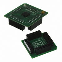
DEMO9S08JM16
Description
BOARD DEMO FOR JM16 FAMI
Manufacturer
Freescale Semiconductor
Type
MCUr
Datasheets
1.DEMO9S08JM16.pdf
(47 pages)
2.DEMO9S08JM16.pdf
(5 pages)
3.DEMO9S08JM16.pdf
(4 pages)
4.DEMO9S08JM16.pdf
(386 pages)
Specifications of DEMO9S08JM16
Contents
Board with Daughter card, Cable, Documentation, Mini-AB USB Kit
Processor To Be Evaluated
MC9S08JM16
Data Bus Width
8 bit
Interface Type
USB
Silicon Manufacturer
Freescale
Core Architecture
HCS08
Core Sub-architecture
HCS08
Silicon Core Number
MC9S08
Silicon Family Name
Flexis - S08JM
Rohs Compliant
Yes
For Use With/related Products
MC9S08JM16
Lead Free Status / RoHS Status
Lead free / RoHS Compliant


2.3.7
The USBDP (D+) and USBDN (D–) pins are the analog input/output lines to/from full-speed internal
USB transceiver. An optional internal pullup resistor for the USBDP pin, R
2.3.8
The MC9S08JM16 series of MCUs support up to 37 general-purpose I/O pins, which are shared with
on-chip peripheral functions (timers, serial I/O, ADC, keyboard interrupts, etc.).
When a port pin is configured as a general-purpose output or a peripheral uses the port pin as an output,
software can select one of two drive strengths and enable or disable slew rate control. When a port pin is
configured as a general-purpose input or a peripheral uses the port pin as an input, software can enable a
pullup device.
For information about controlling these pins as general-purpose I/O pins, see the
Input/Output.”
appropriate module chapter.
Immediately after reset, all pins are configured as high-impedance general-purpose inputs with internal
pullup devices disabled.
Freescale Semiconductor
USB Data Pins (USBDP, USBDN)
General-Purpose I/O and Peripheral Ports
When an alternative function is first enabled, it is possible to get a spurious
edge to the module, user software must clear out any associated flags before
interrupts are enabled.
are enabled. The highest priority module will have control over the pin.
Selecting a higher priority pin function with a lower priority function
already enabled can cause spurious edges to the lower priority module.
Disable all modules that share a pin before enabling another module.
For information about how and when on-chip peripheral systems use these pins, see the
MC9S08JM16 Series Data Sheet, Rev. 2
Table 2-1
illustrates the priority if multiple modules
NOTE
PUDP
Chapter 2 Pins and Connections
, is available.
Chapter 6, “Parallel
29
Related parts for DEMO9S08JM16
Image
Part Number
Description
Manufacturer
Datasheet
Request
R

Part Number:
Description:
Manufacturer:
Freescale Semiconductor, Inc
Datasheet:
Part Number:
Description:
Manufacturer:
Freescale Semiconductor, Inc
Datasheet:
Part Number:
Description:
Manufacturer:
Freescale Semiconductor, Inc
Datasheet:
Part Number:
Description:
Manufacturer:
Freescale Semiconductor, Inc
Datasheet:
Part Number:
Description:
Manufacturer:
Freescale Semiconductor, Inc
Datasheet:
Part Number:
Description:
Manufacturer:
Freescale Semiconductor, Inc
Datasheet:
Part Number:
Description:
Manufacturer:
Freescale Semiconductor, Inc
Datasheet:
Part Number:
Description:
Manufacturer:
Freescale Semiconductor, Inc
Datasheet:
Part Number:
Description:
Manufacturer:
Freescale Semiconductor, Inc
Datasheet:
Part Number:
Description:
Manufacturer:
Freescale Semiconductor, Inc
Datasheet:
Part Number:
Description:
Manufacturer:
Freescale Semiconductor, Inc
Datasheet:
Part Number:
Description:
Manufacturer:
Freescale Semiconductor, Inc
Datasheet:
Part Number:
Description:
Manufacturer:
Freescale Semiconductor, Inc
Datasheet:
Part Number:
Description:
Manufacturer:
Freescale Semiconductor, Inc
Datasheet:
Part Number:
Description:
Manufacturer:
Freescale Semiconductor, Inc
Datasheet: