DEMO9S08JM16 Freescale Semiconductor, DEMO9S08JM16 Datasheet - Page 370
DEMO9S08JM16
Manufacturer Part Number
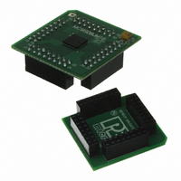
DEMO9S08JM16
Description
BOARD DEMO FOR JM16 FAMI
Manufacturer
Freescale Semiconductor
Type
MCUr
Datasheets
1.DEMO9S08JM16.pdf
(47 pages)
2.DEMO9S08JM16.pdf
(5 pages)
3.DEMO9S08JM16.pdf
(4 pages)
4.DEMO9S08JM16.pdf
(386 pages)
Specifications of DEMO9S08JM16
Contents
Board with Daughter card, Cable, Documentation, Mini-AB USB Kit
Processor To Be Evaluated
MC9S08JM16
Data Bus Width
8 bit
Interface Type
USB
Silicon Manufacturer
Freescale
Core Architecture
HCS08
Core Sub-architecture
HCS08
Silicon Core Number
MC9S08
Silicon Family Name
Flexis - S08JM
Rohs Compliant
Yes
For Use With/related Products
MC9S08JM16
Lead Free Status / RoHS Status
Lead free / RoHS Compliant


1
Appendix A Electrical Characteristics
If the Freescale S08USBV1 implementation has electrical characteristics that deviate from the standard or
require additional information, this space would be used to communicate that information.
18.5
Electromagnetic compatibility (EMC) performance is highly dependant on the environment in which the
MCU resides. Board design and layout, circuit topology choices, location and characteristics of external
components as well as MCU software operation all play a significant role in EMC performance. The
system designer can consult Freescale applications notes such as AN2321, AN1050, AN1263, AN2764,
and AN1259 for advice and guidance specifically targeted at optimizing EMC performance.
18.5.1
Microcontroller radiated RF emissions are measured from 150 kHz to 1 GHz using the TEM/GTEM Cell
method in accordance with the IEC 61967-2 and SAE J1752/3 standards. The measurement is performed
with the microcontroller installed on a custom EMC evaluation board while running specialized EMC test
software. The radiated emissions from the microcontroller are measured in a TEM cell in two package
orientations (North and East). For more detailed information concerning the evaluation results, conditions
and setup, please refer to the EMC evaluation report for this device.
The maximum radiated RF emissions of the tested configuration in all orientations are less than or equal
to the reported emissions levels.
370
Radiated emissions,
electric field
The reported emission level is the value of the maximum emission, rounded up to the next whole number, from among the
measured orientations in each frequency range.
Regulator operating voltage
VREG output
V
VREG disabled
VREG Quiescent Current
USB33
Parameter
EMC Performance
Radiated Emissions
input with internal
Table A-16. Internal USB 3.3V Voltage Regulator Characteristics
V
Symbol
RE_TEM
MC9S08JM16 Series Data Sheet, Rev. 2
Symbol
V
V
Table 18-8. Radiated Emissions
V
usb33in
I
regout
VRQ
regin
V
Conditions
T
A
DD
= +25
= 5.0 V
o
C
Unit
mA
V
V
V
500 – 1000 MHz
150 – 500 MHz
0.15 – 50 MHz
50 – 150 MHz
Frequency
SAE Level
IEC Level
Min
3.9
—
3
3
4 MHz crystal
20 MHz Bus
f
OSC
/f
Typ
3.3
3.3
0.5
—
BUS
Freescale Semiconductor
Level
(Max)
11
–2
N
7
2
2
Max
5.5
3.6
3.6
—
1
dBμV
Unit
—
—
Related parts for DEMO9S08JM16
Image
Part Number
Description
Manufacturer
Datasheet
Request
R

Part Number:
Description:
Manufacturer:
Freescale Semiconductor, Inc
Datasheet:
Part Number:
Description:
Manufacturer:
Freescale Semiconductor, Inc
Datasheet:
Part Number:
Description:
Manufacturer:
Freescale Semiconductor, Inc
Datasheet:
Part Number:
Description:
Manufacturer:
Freescale Semiconductor, Inc
Datasheet:
Part Number:
Description:
Manufacturer:
Freescale Semiconductor, Inc
Datasheet:
Part Number:
Description:
Manufacturer:
Freescale Semiconductor, Inc
Datasheet:
Part Number:
Description:
Manufacturer:
Freescale Semiconductor, Inc
Datasheet:
Part Number:
Description:
Manufacturer:
Freescale Semiconductor, Inc
Datasheet:
Part Number:
Description:
Manufacturer:
Freescale Semiconductor, Inc
Datasheet:
Part Number:
Description:
Manufacturer:
Freescale Semiconductor, Inc
Datasheet:
Part Number:
Description:
Manufacturer:
Freescale Semiconductor, Inc
Datasheet:
Part Number:
Description:
Manufacturer:
Freescale Semiconductor, Inc
Datasheet:
Part Number:
Description:
Manufacturer:
Freescale Semiconductor, Inc
Datasheet:
Part Number:
Description:
Manufacturer:
Freescale Semiconductor, Inc
Datasheet:
Part Number:
Description:
Manufacturer:
Freescale Semiconductor, Inc
Datasheet: