DEMO9S08JM16 Freescale Semiconductor, DEMO9S08JM16 Datasheet - Page 35
DEMO9S08JM16
Manufacturer Part Number
DEMO9S08JM16
Description
BOARD DEMO FOR JM16 FAMI
Manufacturer
Freescale Semiconductor
Type
MCUr
Datasheets
1.DEMO9S08JM16.pdf
(47 pages)
2.DEMO9S08JM16.pdf
(5 pages)
3.DEMO9S08JM16.pdf
(4 pages)
4.DEMO9S08JM16.pdf
(386 pages)
Specifications of DEMO9S08JM16
Contents
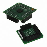
Board with Daughter card, Cable, Documentation, Mini-AB USB Kit
Processor To Be Evaluated
MC9S08JM16
Data Bus Width
8 bit
Interface Type
USB
Silicon Manufacturer
Freescale
Core Architecture
HCS08
Core Sub-architecture
HCS08
Silicon Core Number
MC9S08
Silicon Family Name
Flexis - S08JM
Rohs Compliant
Yes
For Use With/related Products
MC9S08JM16
Lead Free Status / RoHS Status
Lead free / RoHS Compliant


To maintain I/O states for pins configured as general-purpose I/O before entering stop2, the user must
restore the contents of the I/O port registers, which have been saved in RAM, to the port registers before
writing to the PPDACK bit. If the port registers are not restored from RAM before writing to PPDACK,
then the pins will switch to their reset states when PPDACK is written.
For pins that were configured as peripheral I/O, the user must reconfigure the peripheral module that
interfaces to the pin before writing to the PPDACK bit. If the peripheral module is not enabled before
writing to PPDACK, the pins will be controlled by their associated port control registers when the I/O
latches are opened.
3.6.3
When the MCU enters any stop mode, system clocks to the internal peripheral modules are stopped. Even
in the exception case (ENBDM = 1), where clocks to the background debug logic continue to operate,
clocks to the peripheral systems are halted to reduce power consumption. Refer to
Mode,” and
Freescale Semiconductor
On-Chip Peripheral Modules in Stop Modes
Section 3.6.1, “Stop3
1
2
3
4
CPU
RAM
Flash
Parallel Port Registers
ADC
ACMP
MCG
IIC
RTC
SCI
SPI
TPM
System Voltage Regulator
XOSC
I/O Pins
USB (SIE and Transceiver)
USB 3.3 V Regulator
USB RAM
Requires the asynchronous ADC clock and LVD to be enabled, else in standby.
If ACGBS in ACMPSC is set, LVD must be enabled, else in standby.
IRCLKEN and IREFSTEN set in MCGC1, else in standby.
RTCPS[3:0] in RTCSC does not equal to 0 before entering stop, else off.
Peripheral
Mode,” for specific information on system behavior in stop modes.
MC9S08JM16 Series Data Sheet, Rev. 2
Table 3-2. Stop Mode Behavior
Optionally On
States Held
Standby
Standby
Stop2
Off
Off
Off
Off
Off
Off
Off
Off
Off
Off
Off
Off
Off
Off
4
Mode
Optionally On
Optionally On
Optionally On
Optionally On
Optionally On
Optionally On
States Held
Standby
Standby
Standby
Standby
Standby
Standby
Standby
Standby
Standby
Standby
Standby
Stop3
Chapter 3 Modes of Operation
Section 3.6.2, “Stop2
1
2
3
4
5
6
35
Related parts for DEMO9S08JM16
Image
Part Number
Description
Manufacturer
Datasheet
Request
R

Part Number:
Description:
Manufacturer:
Freescale Semiconductor, Inc
Datasheet:
Part Number:
Description:
Manufacturer:
Freescale Semiconductor, Inc
Datasheet:
Part Number:
Description:
Manufacturer:
Freescale Semiconductor, Inc
Datasheet:
Part Number:
Description:
Manufacturer:
Freescale Semiconductor, Inc
Datasheet:
Part Number:
Description:
Manufacturer:
Freescale Semiconductor, Inc
Datasheet:
Part Number:
Description:
Manufacturer:
Freescale Semiconductor, Inc
Datasheet:
Part Number:
Description:
Manufacturer:
Freescale Semiconductor, Inc
Datasheet:
Part Number:
Description:
Manufacturer:
Freescale Semiconductor, Inc
Datasheet:
Part Number:
Description:
Manufacturer:
Freescale Semiconductor, Inc
Datasheet:
Part Number:
Description:
Manufacturer:
Freescale Semiconductor, Inc
Datasheet:
Part Number:
Description:
Manufacturer:
Freescale Semiconductor, Inc
Datasheet:
Part Number:
Description:
Manufacturer:
Freescale Semiconductor, Inc
Datasheet:
Part Number:
Description:
Manufacturer:
Freescale Semiconductor, Inc
Datasheet:
Part Number:
Description:
Manufacturer:
Freescale Semiconductor, Inc
Datasheet:
Part Number:
Description:
Manufacturer:
Freescale Semiconductor, Inc
Datasheet: